
User's Manual
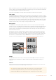
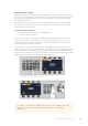
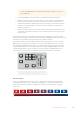

Joystick and Numeric Keypad
The number pad is used to enter numerical data. For example, the number pad can be used
to enter a numerical value for transition duration. When entering data using the number pad,
the soft buttons below each parameter are used to apply the entered data to that parameter.
The Joystick is a 3-axis joystick that is used to size and position keys, DVEs and other elements.
You can also use the joystick to control VISCA PTZ remote cameras.
HOME
MIX
FTB
MACRO
SETTINGS
WIPE
MEDIA
PLAYERS
SUPER
SOURCE
KEYS
DVE
BORDER
CAMERA
CONTROL
STINGER
COLOR
AUDIO
DIP
AUX
1
4
7
ENTER
2
5
8
0
3
6
9
RESET
PROGRAM
PREVIEW
SHIFT MACRO
BKGD
KEY 1
KEY 2
KEY 4
KEY 3
ON
ON
ON
ON M/E 1 M/E 2
M/E 3
M/E 4
SHIFT DIP
DVE
STING
DSK 1
TIE
DSK 2
TIE
DSK 1
CUT
DSK 2
CUT
DSK 1
AUTO
DSK 2
AUTO
FTB
MIX
CUT
AUTO
WIPE
ARM
PREV
TRANS
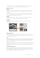
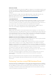
Joystick Control
Controlling Cameras using the Joystick
The joystick can also be used to control a remote camera head using the common VISCA
protocol when connected to your switcher.
PTZ, or ‘pan, tilt, zoom’, control is an extremely powerful tool for controlling pan, tilt and zoom
on remote cameras. You can easily control a bank of cameras one at a time by pressing the
camera control button and then selecting each camera via the numbered buttons on the
numeric keypad. Make your pan and tilt adjustments with the joystick.
You can also choose the tilt direction of your joystick by selecting ‘inverted’ or ‘normal’ in the
‘VISCA control settings. Selecting ‘inverted’ will reverse the tilt action of your joystick.
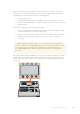
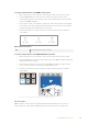
Connecting a Remote Head
Your ATEM Advanced Panel communicates with remote heads via your ATEM switcher’s RS-422
port labeled ‘remote’ or ‘RS-422 serial out’. After connecting your ATEM Broadcast Panel to
your ATEM switcher via Ethernet, connect your ATEM switcher to the RS-422 input on the
remote camera head. RS-422 ports are typically DB-9/DE-9 serial ports, or RJ12 connectors that
look similar to a standard landline phone connector.
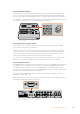
You’ll also need to make sure the remote behavior for your switcher’s RS-422 port is set to
‘PTZ in the ‘settings’ LCD menu.
When connecting more than one remote head, they will normally be daisy chained together via
the RS-422 outputs/inputs between each head.
PUSH PUSH
ANALOG AUDIO INPGMREF IN
MULTI-VIEWAUX
MULTI-VIEW
CH 1 CH 2
SDI INPUTS
SDI OUTPUTS
HDMI INPUTS
1 2 3 4
REMOTE
5 6 7 8
5 6 7 8
USB 2.0
CONTROL
Studio Cam 1
90%
AUX
MENU
SET
FTB
MP 2
AUTO
DSK 1
MIX
MP 1
CUT
ON ON ON ON ON ON ON ON
AFV AFV AFV AFV AFV AFV AFV AFV
1 2 876543
PUSH PUSH
ANALOG AUDIO INPGMREF IN
MULTI-VIEWAUX
MULTI-VIEW
CH 1 CH 2
SDI INPUTS
SDI OUTPUTS
HDMI INPUTS
1 2 3 4
REMOTE
5 6 7 8
5 6 7 8
USB 2.0
CONTROL
Studio Cam 1
90%
AUX
MENU
SET
FTB
MP 2
AUTO
DSK 1
MIX
MP 1
CUT
ON ON ON ON ON ON ON ON
AFV AFV AFV AFV AFV AFV AFV AFV
1 2 876543
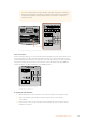
Connect a remote camera head to your ATEM switcher via the
RS-422 port labelled ‘remote’ on the rear panel
104Using ATEM Hardware Panels