Installation and Operation Manual ATEM Production Studio Switchers June 2019 English, 日本語, Français, Deutsch, Español, 中文, 한국어, Русский, Italiano and Türkçe.
Languages To go directly to your preferred language, simply click on the hyperlinks listed in the contents below.
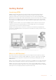
English Welcome Thank you for purchasing an ATEM switcher for your live production work! If you’re new to live production switchers, then you’re about to become involved in the most exciting part of the television industry and that’s live production! There is nothing like live production and it’s so easy to become addicted to the adrenaline rush of editing in real time while the live event unfolds before your eyes.
Contents ATEM Production Studio Switchers Getting Started 6 Media Manager 42 Introducing ATEM 6 Audio Mixer 43 What is an M/E Switcher? 6 Camera Control 44 What is an A/B Direct Switcher? 8 Switcher Settings 44 Understanding the ATEM Switcher 9 Using the Software Control Panel 45 Plugging in Multi View Monitoring 10 Mix Effects 45 Plugging in an ATEM Hardware Panel 11 Program Bus Source Select Buttons 46 Installing Blackmagic ATEM Software on Mac 13 Preview Bus So
Controlling HyperDecks with ATEM Hardware Panels 89 Pattern Key 165 Performing an Upstream Pattern Key 166 Using ATEM Hardware Panels 97 DVE Key 168 Using the ATEM 1 M/E Advanced Panel 98 Performing an Upstream DVE Key 169 99 Key Masking 171 Fly Key 171 Performing Upstream Keyer Transitions 171 173 Using the Control Panel Button Mapping 106 Performing Transitions using ATEM Hardware Panels 106 Performing Downstream Keyer Transitions Cut Transitions 107 Using Adobe
Getting Started Introducing ATEM ATEM Production Studio Switchers are professional broadcast grade digital production switchers capable of switching and processing a variety of video sources in live video production and broadcast environments.
The M/E style of operation has been developed over decades to help eliminate errors when switching live events and is a broadcast standard. It’s extremely easy to see what’s going on at any time so you don’t get confused and make mistakes. The M/E style of operation lets you check the sources you are about to switch on air, as well as try effects before using them on air. You can see buttons for each keyer and transition, so you instantly know what’s going on and what’s about to happen.
Another great advantage of the ATEM M/E style of operation is you can tie keyers to the transition. This means when you do a mix transition, you can also fade on or off keyers at the same time. This allows you to build up a composition and then bring the whole lot on air at the same time. This is what the next transition buttons do and you can select background for normal transitions, or select one or more keyers to transition them on air.
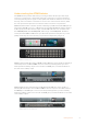
Understanding the ATEM Switcher The ATEM switcher provides all the video processing as well as all video input and output connectors, connection for control panels and power connections. You use the switcher by connecting and using various types of control panels. This allows the switcher to be located remotely, such as in machine rooms where it’s closer to the connected video devices, while the control panel can be placed in a location from where it is easier to run production.
ATEM 2 M/E Production Studio 4K supports SD, HD and Ultra HD video and is capable of switching 20 external inputs from its SDI and HDMI connectors. Input 1 is selectable between the HDMI Input 1 and SDI Input 1 connector. The front panel keypad allows on-the-fly selection of the 6 auxiliary output sources and the large LCD gives instant confirmation of your aux output content.
You should see 8 video boxes at the bottom, and two larger boxes at the top, all bound by white borders. Each box will have a label. If you see this video output, then your ATEM is powered on and running fine! All you need to do now is plug in some control panels and video sources so you can start using your switcher! If you don’t see the multi view output on your television, check the connections and cables are correct. You need to plug into the multi view connector on the rear of the ATEM.
If everything is working fine, you should see the lights on the Ethernet port start to flicker, and the broadcast panel should come alive with buttons illuminated, and the main display on the panel should say ‘ATEM Production Switcher’. The power status indicator lights on the front of the panel will also illuminate. On the ATEM 1 M/E Advanced Panel, the LCD will show the source names for sources switched to the program and preview outputs, plus other settings.
Installing Blackmagic ATEM Software on Mac Before installing any software you will need administrator privileges. It is also a good idea to uninstall any previous versions of ATEM software present on your computer. 1 Ensure you have the very latest driver. Visit www.blackmagicdesign.com/support 2 Open the “Blackmagic ATEM Switchers” folder from the disc or downloaded disk image and launch the “Blackmagic ATEM Switchers Installer Software”.
On Mac, all the files needed to run your ATEM switcher will be installed into a folder called Blackmagic ATEM Switchers in the Applications folder. In the Blackmagic ATEM Switchers folder, you will see ATEM Software Control and Blackmagic ATEM Setup.
In the ATEM Switchers folder, you will see ATEM Software Control and Blackmagic ATEM Setup. ATEM Software Control is the software control panel for your switcher, which also allows loading graphics into the switcher media pool, changing settings, mixing audio, recording macros and controlling Blackmagic cameras including Blackmagic Studio Camera, Micro Studio Camera, and URSA Mini.
After you have made your selection, click ‘continue’. ATEM Software Control will remember these settings the next time it is launched. The software will now automatically search for your ATEM switcher. If an earlier version of your switcher’s internal software is detected, you will be prompted to update. Simply follow the prompts, or refer to the ‘updating the software’ section for more information.
Manually setting the IP address for your Windows computer. Switcher Settings Now you have the software control working, you’ll need to apply your switcher settings. Click on the gear icon on the lower left side of the interface to open the settings window of the ATEM Software Control. Set the switcher video standard You can set the video standard to suit the region in which you are broadcasting, such as 2160p29.97, 1080i59.94, 720p59.94 or 525i59.94 NTSC if you are broadcasting in NTSC based countries.
Set Audio Preferences The ‘audio’ tab lets you select which outputs to use for audio monitoring. You can also mute incoming talkback on SDI inputs and outputs prevent a potential feedback loop in the talkback channels. Audio Settings ATEM Television Studio HD, ATEM Television Studio Pro HD and ATEM Television Studio Pro 4K models also feature mix minus settings on SDI outputs 5 to 8 so you can mute the corresponding input from its program return output.
Set Video Inputs and Labels Customize the Multi View ATEM switchers have 10 input views in the multi view arranged as 2 large views and 8 small views, and ATEM Constellation 8K has additional options for 4, 7, 13 or 16 input views. This lets you select from a range of external and internal sources to display on these views. Click the menus to select what you want on each view.
Customize the multi view for ATEM Constellation 8K. Audio meters can be turned on or off within each source view, or all at once, by clicking on the respective icons in each view or the ‘all on’ button, respectively. You can also turn the safe area guides in the preview window on or off by clicking the respective icon. Connect a HyperDeck If you are running ATEM 6.8 or newer, you can connect up to four HyperDeck disk recorders to your ATEM switcher.
Select the Control Panel You can use ATEM Software Control’s M/E 1 Control Panel with any ATEM switcher. The panel is compact enough to fit on smaller displays including on notebooks. If you have an ATEM 2 M/E Production Switcher and a 1920 x 1080 or larger computer display, you can use the full size M/E 2 Control Panel to see the full set of buttons at once. Simply maximise the control panel to full screen, or resize the window until both panels are revealed.
If you’re plugging a computer with HDMI compatibility into the HDMI inputs of an ATEM switcher, then be sure that the monitor settings on the computer are set to the correct resolution and frame rate. For example, if you are using 4320p video, then your monitor needs to be set to 4320 x 7680 resolution, and if using Ultra HD 2160p video then set your monitor to 3840 x 2160. For 1080i your monitor should be set to 1920 x 1080.
It’s worth noting that if you use your ATEM on a network, then you’re also increasing the complexity of the connection between your control panel and the switcher, so there is possibly a greater chance of something going wrong. However, ATEM can be used when plugged into a switch, and even via most VPNs and over the internet. To allow communication over Ethernet, the IP addresses of the switcher, broadcast panel and any computer running ATEM Software Control needs to be configured correctly.
Change network setting using the ‘configure’ tab in Blackmagic ATEM Setup. Understanding ATEM Hardware Panel Network Settings The hardware panel’s network settings are configured from the network setup menu in the hardware panel’s system control. Along with its own IP address, the hardware panel also needs to be configured with the network location of the switcher, so that communication between the two devices can be established over the Ethernet connection.
This does not change the IP address of the switcher itself. It just changes where the control panel is looking to find the switcher. If the control panel cannot find the switcher, then you might need to check the switcher to see if it’s been set correctly. To change the IP address of the switcher, connect the switcher via USB to a computer and run Blackmagic ATEM Setup as described previously in this manual. Home Menu ATEM 1 M/E Production Switcher Control Panel Connected OK Panel IP Address: 192.168.10.
NOTE Changing the switcher IP address on your panel does not change the IP address of the switcher itself. It just changes where the control panel is looking to find the switcher. If the control panel cannot find the switcher, then you might need to check the switcher to see if it’s been set correctly. To change the IP address of the switcher, connect the switcher via USB to a computer and run Blackmagic ATEM Setup as described previously in this manual.
4 If you have elected to use a fixed IP address, you now need to set this IP address by selecting the PANEL IP menu button and use the knobs or the numeric keypad to edit each field as required. Changing this IP address may cause the panel to lose communication. 5 If the subnet mask and gateway address need to be set, then select the relevant buttons on the system control buttons to set and use knobs or the numeric keypad to edit.
4 If you have elected to use a fixed IP address, you now need to set this IP address by adjusting the corresponding soft control knobs for each field of the IP address. You can also use the numeric keypad. Changing this IP address may cause the panel to lose communication. 5 If the subnet mask and gateway address need to be set, then press the right arrow button in the system control buttons to progress through each setting menu, and use the knobs or the numeric keypad to edit.
If you can communicate successfully with your camera operators and engineering personnel, you can then adjust the headset monitoring levels to your preference. This is achieved by pressing each talkback channel to activate it, for example ‘Prod Talk’ and then pressing the channel volume up and down arrows to adjust its monitoring level. This lets you mix the levels so you can comfortably hear exactly what you need to hear.
ATEM Software Installer Updating the Switcher Software 1 Connect the switcher via the USB port. If your switcher is running ATEM software 6.6 or later and you already have your switcher connected to your computer via Ethernet, you can update via the Ethernet connection. When upgrading software via USB, make sure the switcher is the only ATEM device connected via USB to the computer running the setup utility software. If more than one ATEM device is connected, the switcher may not be recognized.
2 Launch Blackmagic ATEM Setup. 3 If the panel requires updating, you will be prompted by a window asking if you would like to update the software. Click ‘update’ to initiate the update process. It’s important you don’t unplug the power from the panel during the software update. 4 Once the software update is complete, a window will prompt you to power cycle your hardware panel. Turn your panel off and on, then click ‘close’ in the dialog box.
Multi View SDI and HDMI Output The multi view outputs on all ATEM switchers are HD except for ATEM 4 M/E Broadcast Studio 4K, which are HD or Ultra HD, and ATEM Constellation 8K, which are HD, Ultra HD or 8K. You can choose from a selection of multi view output formats and frame rates. This feature increases compatibility with a wider range of monitors, plus you can output your multi view in Ultra HD even if you are working in regular HD.
NOTE SDI outputs for ATEM Constellation 8K can have any source routed to them. For maximum flexibility, you can route any internal or external video source to any of its 24 HD or Ultra HD outputs, or any of its six 8K outputs. Video sources can include program, clean feed, preview, M/E output, as well as cameras and other external equipment. 8K SDI inputs and outputs on ATEM Constellation 8K use the two sample interleave technique, also known as 2SI.
6 6 To perform a transition: 1 Select the next source by pressing button 4. The button will now illuminate green to show it’s selected on the preview bus. 2 Press the cut or auto buttons. If you press cut, button 4 will now illuminate red as it’s on air. Input 4 will also be switched to the program output. If you select auto, then the currently selected transition will be triggered.
Selecting Other Sources You can select other sources in the switcher that are not on the front panel from the LCD menus. To select an alternative program source: 1 Press the menu button to display the menus. 2 Scroll with the knob through the menus to the ‘program source’ menu. 3 Press the ‘set’ button and you will see the program source menu page will be selected. 4 Scroll down the list of sources in the ‘program source’ menu until you get to the one you want.
However, there is another change to the front panel in cut bus mode and that’s the behavior of the cut and auto buttons. Now the inputs are selected the instant you press them, the cut and auto buttons don’t trigger the transition anymore. What they are now used for is to select the type of transition you want when you press the input buttons.
If you want to adjust the audio for each of the SDI inputs, you can view and adjust the audio levels individually through the menus on the LCD. This is a useful way to identify when the main audio level is too high because single input is too high level. In this case you don’t want to adjust the master audio level because all the other inputs will now become too low. You really want to select the input audio level and adjust just that single audio level.
Fade to Black When you start or finish a program, you want to be able to fade to black without worrying about leaving a logo on the screen by accident. Your ATEM switcher has a lot of powerful features and lots of layers that you can enable for transitions. What this means is you could have a complex setup on the switcher with many layers but you really just want a single button to start your program. This is what the FTB or fade to black button does.
7 17 8 18 9 19 10 5 Select it by pressing the set button. 6 Scroll through the list of options for this menu item. 7 Press set when you want to make the desired setting active. 8 Press menu a few times to go back to the main video preview screen. KEY 1 MIX DSK 1 MIX DSK 2 MIX FTB BARS BLACK MP1 MP2 MIX WIPE DIP DVE 20 27 28 29 30 37 38 39 40 CUT AUTO Audio Mixer +2.00db Master Level Source Input LOCK MENU Camera 1 Level +2.00db Camera 2 Level +2.
Using ATEM Software Control The ATEM Software Control is included with your ATEM switcher, and allows you to control your switcher in a similar way to a full hardware control panel. However instead of menu buttons, it uses a range of palettes on the right side that shows you all processing features of your production switcher and allows settings to be easily made. You can also use the ATEM Software Control to configure your switcher settings as well as upload graphics and manage the media pool.
Button Mapping In the mapping preferences, you can assign inputs to specific buttons on the preview and program rows. The camera drop down menu lets you select a ‘Blackmagic SDI’ camera for each input, or you can select ‘none’ if you don’t have a camera connected to the input. ATEM software and hardware control panels support button mapping so you can assign your most important sources, especially cameras, to the most accessible buttons in the program and preview rows.
Mouse or Trackpad Operation The virtual buttons, sliders and fader bar on the Software Control Panel are operated using your computer mouse or a trackpad if you’re using a laptop. To activate a button, click once with the left mouse button. To activate a slider, click and hold down the left mouse button while dragging. Similarly, to control the fader bar, click and hold down the left mouse button on the fader bar handle and drag up or down.
For example, your ATEM 4 M/E Broadcast Studio 4K could have the maximum 64 still graphics and 2 clips loaded that will be used on your live production and then you can assign each of the media players to various stills as you work. As you take a graphic off air, you can change the media player graphic to the next graphic you want, and then you can put that media player back on air with the new graphic. ATEM Constellation 8K holds clips up to 100 frames long and has one media player in 8K mode.
Camera Control The Camera tab in the software is where you can control cameras remotely, in a similar way to how traditional external camera control units can control cameras, however with ATEM switchers, this functionality is built into the software so it’s always available.
and broadcast studio switchers, the arrangement for the 8 smaller video views are fully routable allowing you to view any source in the switcher. ATEM Constellation 8K is even more flexible, giving you the option to customize the multi view to show any combination of 4, 7, 10, 13 or 16 sources in the switcher. This lets you monitor cameras, internal sources, media players and even aux outputs on a single monitor.
Program Bus Source Select Buttons The program bus source select buttons are used to hot switch background sources to the program output. The source currently on air is indicated by a button that is illuminated red. Preview Bus Source Select Buttons The preview bus source select buttons are used to select a background source on the preview output, this source is sent to the program bus when the next transition occurs. The currently selected preview source is indicated by a button that is illuminated green.
CUT The CUT button performs an immediate transition of the program and preview outputs, overriding the selected transition style. AUTO/RATE The AUTO button will perform the selected transition at the rate specified in the ‘rate’ display. The transition rate for each transition style is set in the transition palette for that style and is displayed in the ‘rate’ window of the transition control block when the corresponding transition style button is selected.
Downstream Keyers TIE The TIE button will enable the DSK on the preview output, along with the next transition effects, and tie it to the main transition control so that the DSK can be taken to air with the next transition. The DSK will transition at the rate specified in the RATE display of the transition control block. If the DSK is tied, the signal routing to the clean feed 1 is unaffected.
Different ATEM models will have different features, so the palettes can change. The palettes also show the order of the processing in the switcher. You can expand and minimize palettes to save space and scroll them up and down to get the adjustments you need to set. Palettes Tab The Palettes tab contains the following processing controls.
With ATEM switchers that have 1 M/E, these keyers are all labeled as being for M/E 1. On ATEM 2 M/E and 4 M/E model switchers, the labels will show which M/E these keys are connected to. Transitions The transitions palette is where you can configure the parameters of each transition style. For example, for the dip transition the palette has a drop down menu where you can select the dip source and for the wipe transition the palette displays all the available wipe patterns.
Hyperdecks If you are running ATEM switchers 6.8 or newer, you can connect up to 4 Blackmagic HyperDeck Studio model disk recorders and control them using ATEM Software Control’s HyperDecks palette. For more information refer to the ‘HyperDeck Control’ section of this manual. TIP The ‘capture’ tab supports legacy ATEM Production Switcher models with USB capture features.
Tally Any source whose audio is on air is lit with a red tally light in the software. External audio is on air by default so the EXT tally light is usually lit red. In the example on this page, Cam4 and Cam7 are lit because their audio is set to be always on. The tally light will be illuminated dull yellow when AFV is selected and the channel’s associated camera is off air. This also applies to the master fader tally light when the master fader AFV button is selected.
The audio meter for Cam1 is shown in gray to indicate that its audio will not be used as neither of its ON or AFV buttons are enabled. Cam2 has AFV selected but its audio is not currently being used as the camera is not on air as is indicated by its dull yellow tally light. Cam4 and Cam7 have their direct mix set to ON so their mixed audio is always used, and their tally lights remain lit, even if another camera is currently on air.
Master Audio Level Output The master fader on the right side of the audio mixer is used to set the gain on the audio level on the SDI and HDMI program outputs and has its own audio level meter. Select the AFV button on the master audio output fader to enable the AFV fade to black feature. This lets you fade your master audio when you click on the Fade to Black button. Audio Mixer Monitor The monitor volume knob and buttons appear below the master fader and control the monitoring audio output behavior.
Headphones settings on ATEM Constellation 8K let you mix the levels of each monitoring output. For example, you may want to increase or decrease the level of the talkback audio against the program audio. Master Adjust the master level slider to set the program audio level in the headset and if you don’t want to listen to program audio, then slide this control fully to the left.
Using the 6 Band Parametric Equalizer Each input and the master output, has a 6 band parametric equalizer which can be used to control specific frequencies. This could include reducing low frequency hum or noise on a microphone input, or boosting the low frequencies on a thin sounding track, or even to add uniqueness to each input so they are more distinct in the final mix. You have many creative options.
Handles Each band handle is positioned along the line curve displayed in the graph. You can click and drag each handle to choose the frequency you wish to adjust for that band and the gain you want to set. When moving a handle with your mouse, both the frequency and gain settings are affected simultaneously, which gives you a fast way to make quick adjustments to each band across the entire range of frequencies. NOTE To make changes using a handle, ensure the band is enabled.
TIP Compare the audio with changes against the original unaltered audio by clicking on the bypass button at the very top of the equalizer window. This lets you turn the equalizer on or off. Band Filters There are six different types of band filters you can choose from. These filters include bell, high shelf, low shelf, notch, high pass and low pass. These filters let you control specific zones within the frequency range.
Combined with equalizer controls, these features are extremely powerful, giving you the ability to precisely shape and define the audio to generally optimize the sound of the master output. This section describes the expander, gate, compressor and limiter controls.
Gating is extremely effective, but it’s also very powerful so requires careful attention. If the gate threshold is set too high it can cause artifacts, such as cutting off the start of a syllable or the quiet end of a word. You can compensate by reducing the threshold slightly, or by increasing the attack or release time. Compressor Compression lets you reduce peaks in an audio signal, reducing the dynamic range of a signal, so you can boost the overall level without clipping.
Control Minimum Default Maximum -50dB -35dB 0dB Ratio 1.0:1 2.0:1 10:1 Attack 0.7ms 1.4ms 30ms Hold 0.0ms 0.0ms 4s Release 50ms 93ms 4s Threshold -50dB -12dB 0dB Attack 0.7ms 0.7ms 30ms Hold 0.0ms 0.0ms 4s Release 50ms 93ms 4s Compressor Compressor Controls Threshold Limiter Limiter Controls * Master Dynamics expander/gate controls are unused in Master Dynamics. ** Master Dynamics expander/gate threshold default is -35dB.
Once all the Fairlight controls are set, you can then increase or decrease the faders on the audio mixer to set them at their best levels for the live mix and make adjustments where necessary during the production. You can also go back to any of the settings and make further adjustments if needed, but it’s best to follow the same order as described above to get the best results from each function.
When dropping a still, clip or audio file into a slot, a progress indicator will show the loading status. You can drop multiple files into the media pool, even if the first images have not yet completed loading, as they will continue to load one after the other. If a clip or still is dropped into a window which already has content loaded, the existing content will be replaced. The ATEM media pool supports PNG, TGA, BMP, GIF, JPEG and TIFF still image formats. Audio files must be WAV, MP3 or AIFF.
Changing Switcher Settings Clicking on the switcher settings ‘gear’ icon will open the settings window where you can change general switcher settings, Multi View, label, HyperDeck and remote settings. These settings are divided into tabs. General Settings Setting the Switcher Video Standard The video setting is used to select the operating video standard of the ATEM switcher and this must be set to the same video standard as the video sources you are plugging into the ATEM switcher.
ATEM currently supports the following video standards: ATEM Constellation 8K ATEM 4 M/E Broadcast Studio 4K ATEM Production Studio 4K Models – – 525i59.94 NTSC 4:3 – – 625i50 PAL 4:3 – – 252i59.94 NTSC 16:9 – – 625i50 PAL 16:9 720p50 720p50 720p50 720p59.94 720p59.94 720p59.94 1080i50 1080i50 1080i50 1080i59.94 1080i59.94 1080i59.94 1080p23.98 1080p23.98 1080p23.98 1080p24 1080p24 1080p24 1080p25 1080p25 1080p25 1080p29.97 1080p29.97 1080p29.
For example if your ATEM is selected to run at 2160p59.94 then the multi view will output at 2160p29.97 when the multi view setting is selected to Ultra HD, or you can choose to output 1080i59.94, 1080p29.97 or 1080p59.94 when the multi view output is selected to regular HD. Set Multi View video standard For all other switcher models the multi view output is always HD even when running in standard definition so you can see all your sources in higher resolution. When switching Ultra HD video at 59.
Setting the Audio Output Behavior The ‘audio’ tab lets you control the audio monitoring settings, such as selecting the program audio or monitor audio via the XLR outputs. Instead of XLR monitor outputs on ATEM Constellation 8K, you can use the MADI out BNC connectors. Program audio is the same audio that the audio mixer sends to the SDI and HDMI program outputs. Monitor settings and solo monitoring are disabled in the audio mixer when program audio is selected.
Adjusting the Media Pool Clip Length For models that support media clips, the media pool features two clips that share the same pool of memory. ATEM Constellation 8K can store two 8K clips and four HD or Ultra HD clips. By default, each clip receives equal amounts of the available memory which determines the maximum number of frames. If you need a clip to be longer, adjust the balance of frames. It’s worth remembering that lengthening one clip will shorten the other.
Multi View Settings The multi view settings allow you to set the multi view orientation. The 8 smaller windows are fully routable so you can monitor any switcher source. By default, external inputs 1 - 8 are routed to multi view source windows 1 to 8, but click the menus to select what sources are viewed on each window! ATEM Constellation 8K has one 8K multi view, or four multi view outputs in HD or Ultra HD. The 8K multi view lets you choose configurations of 4, 7, 10, 13 or 16 views.
Multi View layout options for ATEM Constellation 8K. Labels Settings The video input settings are used to select the inputs and change labels. Depending on your ATEM switcher model, some video inputs can select between different video sources, such as HDMI or SDI. You can identify switchable connections on the rear of the switcher because all inputs are numbered and any inputs that can switch will have the same input number on their label.
Inputs can have customized labels and these labels appear on ATEM broadcast control panels and on the multi view. Long and short labels need to be entered, as long labels are often too long to be displayed on broadcast control panel’s smaller displays. A short 4 character name is used to identify the video input on the source names display of the broadcast panel.
Set the RS-422 remote port to disabled, VISCA and GVG Controlling Auxiliary Outputs Auxiliary outputs are separate SDI outputs on some ATEM switcher models that can have various inputs and internal sources routed to them. They are very similar to router outputs and all video inputs, color generators, media players, program, preview and even color bars can be output. Most ATEM models provide for 1 - 6 auxiliary outputs.
Saving and Restoring Switcher Settings ATEM Software Control lets you save and restore either specific settings, or all of the switcher settings you have created. This powerful feature is incredibly time saving on live productions where regular settings are used. For example, you can immediately restore saved camera settings, lower third graphics and detailed key setups from a laptop or USB drive. Saving settings menu.
Restoring your Settings 1 Go to the menu bar in ATEM Software Control and select File>Restore. 2 A window will ask for the file you want to open. Select your save file and click Open. 3 You’ll now see a window containing active checkboxes for your saved settings on each block of your ATEM switcher. Leave Select All enabled to restore all your saved settings, or select only the checkboxes for the settings you want to restore. 4 Click Restore.
When controlling cameras, the ATEM switcher control works by broadcasting camera control packets via all the non down converted SDI outputs of your ATEM switcher. So this means you can connect an SDI output of your ATEM switcher to the camera’s video inputs and the camera will detect the control packets in the SDI link and allow you to control features in the camera itself.
Connecting via Optical Fiber 1 Connect the Blackmagic Camera’s optical out/in to the optical out/in on an ATEM Studio Converter or Talkback Converter 4K. You’ll need to have SMPTE compatible optical fiber SFP modules installed in your Studio Camera and ATEM converter to connect via optical fiber. 2 Connect a suitable SDI out from your ATEM converter to any SDI input on your ATEM switcher.
Channel Status The channel status at the top of each camera controller displays the camera label, On Air indicator and lock button. Press the lock button to lock all the controls for a specific camera. When on air, the channel status illuminates red and displays the On Air alert.
Detail Use this setting to sharpen the image from your cameras live. Decrease or increase the level of sharpening by selecting: Detail off, detail default for low sharpening, medium detail and high detail. Color Wheel The color wheel is a powerful feature of the DaVinci Resolve color corrector and used to make color adjustments to each YRGB channel’s lift, gamma and gain settings. You can select which setting to adjust by clicking on the three selection buttons above the color wheel.
The iris/pedestal control illuminates red when its respective camera is on air. Zoom Control When using compatible lenses with an electronic zoom feature, you can zoom your lens in and out using the Zoom control. The controller works just like the zoom rocker on a lens, with telephoto on one end and wide angle on the other. Click on the zoom control, located above the Coarse slider and drag up to zoom in, or drag down to zoom out.
Click on the auto focus button or drag the manual focus adjustment left or right to focus a compatible lens. Manual Focus Adjustment When you want to adjust the focus on your camera manually, you can use the focus adjustment located at the bottom of each camera controller. Drag the wheel control left or right to manually adjust focus while viewing the video feed from the camera to ensure your image is nice and sharp. Camera Gain The camera gain setting allows you to turn on additional gain in the camera.
DaVinci Resolve Primary Color Corrector If you have a color correction background, then you can change your camera control from a switcher style CCU interface to a user interface that’s more like a primary color corrector on a post production color grading system. Blackmagic cameras feature a DaVinci Resolve primary color corrector built in. If you have used DaVinci Resolve, then creatively, grading in the Blackmagic camera will be identical so you can use your color grading experience for live production.
Double-click within the color ring Resets the color adjustment without resetting the master wheel adjustment for that control. Click the reset control at the upper-right of a color ring Resets both the color balance control and its corresponding master wheel. Master Wheels Use the master wheels below the color wheels to adjust each YRGB channels’ lift, gamma and gain controls. Adjust the master wheels by dragging the wheel control left or right.
Lum Mix Setting The color corrector built into Blackmagic cameras is based on the DaVinci Resolve primary color corrector. DaVinci has been building color correctors since the early 1980’s and most Hollywood films are color graded on DaVinci Resolve than any other method. This means that your color corrector built into the camera has some unique and creatively powerful features. The YRGB processing is one of those features. When color grading, you can choose to use RGB processing, or YRGB processing.
Making Color Correction Adjustments The DaVinci Resolve Micro panel is primarily designed for use with DaVinci Resolve software, but you can also use it to make adjustments in the color corrector panel of ATEM Software Control in the following way: The Trackballs The three trackballs control the lift, gamma and gain color wheels in the color corrector panel. The ring surrounding each trackball adjusts the corresponding master wheels beneath the color wheels.
HyperDeck Control Introducing HyperDeck Control If you are running ATEM Switchers software 6.8 or newer, you can connect up to 4 Blackmagic HyperDeck Studio disk recorders to your switcher and control them using the HyperDecks palette in ATEM Software Control, or from the system control buttons on an ATEM broadcast panel.
DC IN TIME CODE REMOTE OUT CHANNELS 1 & 2 CHANNELS 3 & 4 OUT 1 ANALOG OUT 2 3 ANALOG OUT 4 IN 1 ANALOG IN 2 3 ANALOG IN 4 IN STEREO IN ANALOG INPUT NTSC / PAL Y L R B/Y REF R-Y MONITOR OUT OUT USB AC IN DIGITAL VIDEO SDI OUT OUT A ETHERNET IN B A 1 1 2 MADI OUT TALKBACK MADI IN CONTROL REMOTE USB REF IN 2 C D C D SDI IN EXT DISK IN 3 4 B 5 8K INPUTS 6 7 8 9 10 1 2 3 8K OUTPUTS 4 5 6 1 5 9 13 17 21 25 29 33 37 1 5 9 13 17
Auto Roll You can set a HyperDeck disk recorder to automatically roll video when it is switched to the program output. For example, you can cue a HyperDeck to the point you want your source to begin, then roll the source by pressing its input button on the mix effects program row. As HyperDecks must buffer a couple of frames before commencing playback, the actual cut will be delayed a preset number of frames to ensure a clean transition. This is just like setting a preroll on a videotape machine.
Choose from up to four HyperDecks by clicking their selection buttons in the HyperDecks palette. In addition to the text color, each HyperDeck’s selection button also has a tally indicator. Green Outline Indicates a HyperDeck that is currently switched to the preview output. Red Outline Indicates a HyperDeck that is currently switched to the program output, meaning it is currently live to air. You may also see one of the following status indicators above the selection buttons for your HyperDecks.
Record Click on this button to start recording on your HyperDeck. Click again to stop recording. Previous Clip Moves to the previous clip in your HyperDeck’s media list. Play Clicking ‘play’ once initiates playback, clicking it again stops playback. If you have ‘auto roll’ enabled in your HyperDeck settings, playback will commence automatically when your HyperDeck is switched to the program output. Next Clip Moves to the next clip in your HyperDeck’s media list.
HyperDeck Setup with ATEM Broadcast Panels Please follow the steps in this section to set up your HyperDeck with an ATEM Broadcast Panel.
4 Press the source button that matches the input that you have connected your HyperDeck to or scroll through your source list using the third control knob under the LED display. Press the ‘save’ soft button to confirm your selection. HYPER DECK 1 HYPER DECK 2 HYPER DECK 3 HYPER DECK 4 INFO INPUT AUTO ROLL HYPER DECK IP SAVE REVERT BACK Use the HyperDeck setup menu to configure connected HyperDecks 5 Once you have specified the source for a given HyperDeck, you will need to set its IP address.
Configuring auto roll: 1 Press the ‘auto roll’ soft button in the HyperDeck Setup system control menu. 2 Toggle auto roll on and off by pressing the soft button under the ‘auto roll’ title in the four line display. 3 When auto roll is enabled, set the number of offset frames by turning the third control knob under the four line display.
Y M/E 1 PATT EFFECTS KEYS TRANS DSK KEYS COLOR M/E 1 KEY BOX 4 BOX 2 PREV TRANS MEDIA PLAYER SHIFT MACRO 1 RECALL RECALL & RUN LOOP RECORD CUT PANEL SETUP 1 2 3 HyperDeck Multi Control on ATEM 2 M/E Broadcast Panels 4 5 6 For quick access, you can also assign one of your HyperDeck disk recorders to your ATEM 2 M/E Broadcast Panel’s multi control.
HyperDeck Setup with ATEM 1 M/E Advanced Panel Once you have connected your HyperDeck to your switcher, as detailed in the ‘connecting HyperDecks’ section, use ATEM 1 M/E Advanced Panel’s system control and LCD soft buttons to setup and control your HyperDecks. To begin, press the system control ‘settings’ button.
Assigning an IP Address Once you’ve assigned an input to a HyperDeck, you’ll need to enter its IP address. This allows ATEM 1 M/E Advanced Panel to control the HyperDeck via Ethernet. To enter a HyperDeck’s IP address, navigate to the third HyperDeck settings page with the ‘left’ or ‘right’ arrow buttons, or pressing ‘3’ on the numeric keypad while in the HyperDeck settings menu. In this page, you’ll see an IP address for the currently selected HyperDeck.
Controlling HyperDecks with ATEM 1 M/E Advanced Panel HyperDeck controls are available in the ‘media players’ menu in your ATEM 1 M/E Advanced Panel. To access this menu, press the ‘media players’ control panel button and press the soft button above the ‘HyperDecks’ indicator to access HyperDeck control. If your switcher has more than two media players, you may need to navigate to the next menu page to access HyperDeck controls.
HOME SETTINGS KEYS MIX WIPE DVE JOG STINGER FTB MEDIA PLAYERS BORDER COLOR MACRO SUPER SOURCE CAMERA CONTROL AUDIO CLIP LENGTH TIME ELAPSED TIME REMAINING 00:00:10:20 00:00:03:08 00:00:07:12 DIP AUX SHUTTLE ... 1-Ready Clip 003 HYPERDECK CLIP JOG SHUTTLE 1 2 3 4 5 6 7 8 9 ENTER 0 RESET In the fourth menu page, press the ‘record’ button to record the program output of your switcher to your HyperDeck.
ATEM 1 M/E Broadcast Panel The ATEM 1 M/E Broadcast Panel is designed for switchers with one mix effects panel, or if you need a hardware panel to control a mix effects panel on a larger ATEM switcher with more than one ME. ATEM 2 M/E Broadcast Panel This hardware control panel is designed to control two mix effects panels individually.
HOME SETTINGS WIPE MIX KEYERS DVE Using the Control Panel MEDIA PLAYERS FTB Mix Effects MACRO SUPER SOURCE STINGER BORDER COLOR CAMERA CONTROL AUDIO DIP AUX 1 2 3 4 5 6 7 8 ENTER 0 9 RESET The program bus, preview bus and source names display are used together to switch sources on the program and preview outputs.
Source Select Bus The source select bus works in conjunction with the source names display and is used to assign sources to auxiliary outputs and keyers. When the macro button is enabled, this row of buttons is also used for loading and running macros recorded to the corresponding slots. The buttons will illuminate blue when the macro button is enabled.
When a transition type is selected, the LCD menu shows the transition rate and provides instant access to all the corresponding settings for that transition type. Use the soft buttons and knobs to navigate through the settings and make changes. The button marked ARM is currently disabled and will be enabled in a future update. PREV TRANS The PREV TRANS button enables the preview transition mode allowing the operator to verify a transition by performing it on the preview output using the fader bar.
R For more information on how to record and run macros using the advanced panel, refer to the ‘Using Macros/Recording Macros using an ATEM 1 M/E Advanced Panel’ section. DIP DSK TIE AUX 3 4 5 6 7 8 ENTER 0 9 RESET Because the tied downstream keyer is now tied to the main transition, the transition will happen at the rate specified in the auto rate setting in the LCD ‘home’ menu. When the DSK is tied, the signal routing to the clean feed 1 is unaffected.
If there are small dot icons on the LCD menu, this means there is more than one page of settings and you can move through the pages by pressing the left and right arrow buttons. For example, to change the border softness on a wipe transition 1 Press the ‘wipe’ button. 2 Press the right arrow button next to the LCD to move to the third page of settings. 3 Rotate the control knob under the ‘softness’ setting to change the softness of the wipe transition border.
Joystick and Numeric Keypad The number pad is used to enter numerical data. For example, the number pad can be used to enter a numerical value for transition duration. When entering data using the number pad, the soft buttons below each parameter are used to apply the entered data to that parameter. The Joystick is a 3-axis joystick that is used to size and position keys, DVEs and other elements. You can also use the joystick to control VISCA PTZ remote cameras.
PTZ Setup for Remote Heads All PTZ setup options are set using the ‘settings’ LCD menu. Press the arrow buttons to move to the last page of switcher settings and set the remote port to VISCA. Set the baud rate to match the rate used by your PTZ camera. Refer to your camera’s support documentation to confirm the appropriate baud rate. Pressing the camera control button opens the camera settings, where you can select VISCA control and choose the camera you want to adjust.
PTZ Control via SDI You can also control PTZ camera heads via SDI. For example, by connecting the program return feed from your switcher to a Blackmagic Micro Studio Camera, then connecting the SDI output from the camera’s expansion cable to your PTZ head, you can control the head via the SDI signal. For more information on PTZ control using a Blackmagic Micro Studio Camera refer to the Blackmagic Studio Cameras manual. This manual can be downloaded from the Blackmagic Design support center at www.
The ATEM 1 M/E Advanced Panel is similar to the broadcast panels with all the same M/E controls. However, the ATEM 1 M/E Advanced Panel uses a large LCD with soft control knobs and buttons which lets you adjust settings dynamically as you control your switcher. This is a fast and convenient way of working with your panel. This section describes how to perform the various transition types on your switcher using an ATEM hardware panel.
CAM 1 CAM 2 CAM 3 1 2 3 4 5 6 TIP It’s recommended to use the transition control block to perform transitions because it provides the opportunity to verify the video content on the preview output before sending it to the program output, for example to verify that a camera is in focus.
TIP On the ATEM 1 M/E Advanced Panel, all transition settings are accessed via the LCD menu. 4 Press the AUTO button in the transition control block to initiate the transition. 5 During the transition, the red and green buttons on the program and preview buses both turn red to indicate that you are in the middle of a transition.
play 2 play 2 play 2 To perform a mix transition on an ATEM broadcast panel 1 On the preview bus, select the video source that you want on the program output. 2 Press the DIP/MIX button to select the mix transition type.3 The system control 1 2 automatically navigates to the transition menu. To manually navigate to the transition menu press HOME > TRANS. 3 In the control system, use the knob to adjust the mix rate. The transition rate display in the transition control block will update dynamically.
For example, the dip transition can be used for a transition that calls for a white flash or a transition that quickly flashes the sponsor logo. The length of the dip transition and the dip source can both be customized. Program output for a dip transition. 2 3 4 5 6 7 8 To perform a dip transition on an ATEM broadcast panel 9 1 On the preview bus, select the video source that you want on the program output. 2 ENTER 0 Press the SHIFT and DIP/MIX buttons to select the dip RESET transition type.
play 2 play 2 play 2 Wipe Transitions A wipe is a transition from one source to another and is achieved by replacing the current source by another source with a pattern that forms a shape. For example an expanding circle or diamond. Program output for a wipe transition. To perform a wipe transition on an ATEM broadcast panel 1 2 3 1 On the preview bus, select the video source that you want on the program output. 2 Press the WIPE button to select the4wipe transition type.
Studio A Cam 1 Studio A Cam 2 Studio A Cam 3 Studio A Cam 4 Studio A Cam 5 Media Player 1 Media Player 2 Replay 1 Replay 2 Remote 1 SHIFT SHIFT DIP MACRO DVE ON PROGRAM MIX BKGD Studio A Cam 1 Studio A Cam 2 Studio A Cam 3 Studio A Cam 4 Studio A Cam 5 Media Player 1 Media Player 2 Replay 1 Studio A Cam 1 Studio A Cam 2 Studio A Cam 3 Studio A Cam 4 Studio A Cam 5 Media Player 1 Media Player 2 Replay 1 Camera 1 Camera 2 Camera 3 Camera 4 Camera 5 Camera 6 Camera 7 Repla
DVE Transitions Your ATEM switcher includes a powerful digital video effects processor for DVE transitions. A DVE transition displaces the image in various ways to transition from one picture to another. For example, a DVE transition can be used to squeeze the current picture off screen revealing a new video under it. To perform a DVE transition on an ATEM broadcast panel 1 On the preview bus, select the video source that you want on the program output.
DVE transition parameters DVE Rate The duration of the DVE transition in seconds and frames. Rotate the DVE rate knob to adjust the DVE transition rate. The new rate is immediately displayed in the transition rate window in the transition control block. Symmetry Symmetry can be used to control the aspect ratio of the pattern. For example, adjusting the symmetry will allow you to change a circle into an ellipse. On the broadcast panel symmetry can be adjusted using the z axis of the joystick.
Performing a Graphic Transition To perform a graphic transition on an ATEM broadcast panel 1 On the ATEM 2 M/E Broadcast Panel, press the DVE button which illuminates yellow. On the ATEM 1 M/E Broadcast Panel, press the SHIFT and WIPE/DVE buttons to select the DVE transition type. The WIPE/DVE button illuminates green to indicate the DVE transition type is selected.
4 Press the auto button to perform the transition as an auto transition, or use the fader bar for a manual transition. Description of graphic wipe parameters Rate Rate specifies the length of the transition in seconds and frames. The rate can be adjusted using the rate knob or by entering a number on the number pad and pressing the set rate button. Normal The normal direction moves the graphic from left to right. Reverse Reverse changes the direction so that it moves the graphic from right to left.
Manual Transitions Manual transitions let you manually transition between program and preview sources using the fader bar in the transition control block. Mix, dip, wipe and DVE transitions can all be performed as a manual transition. To perform a manual transition 1 On the preview bus, select the video source that you want on the program output. 2 Select the transition type using the transition type buttons in the transition control block.
1 2 3 4 KEY 1 LUMA KEY KEY 2 CHROMA KEY KEY 3 PATTRN KEY KEY 4 DVE LUMA KEY MASK MENU CHROMA KEY PATTRN KEY MASK MENU 41 52 63 74 85 96 HOME CAM 7 08 CLR 9 HOME CAM 0 CLR DVE Control Panel Main ON CUT FILL CUT FILL ON ON ON ON ON ON ON BKGD KEY 1 KEY 2 KEY 3 KEY 4 BKGD KEY 1 KEY 2 KEY 3 KEY 1 KEY 2 LUMA KEY CHROMA KEY MASK MENU DIP DVE MIX WIPE Backup Control Panel KEY 3 KEY 4 PATTRN KEY DVE KEY 4 HOME DSK 1 TIE DSK 2 TIE DSK 1 TIE DSK 2 TIE M
KEY 1 LUMA KEY MASK MENU The 8 character destination display and select bus together show you the routing of sources to keys and auxiliary outputs. The currently selected source is indicated by an illuminated button. A blinking button indicates a shifted source. A green illuminated button identifies a protected source. Protected sources are program, preview, clean feed 1 and clean feed 2.
KEY 3 ATTRN KEY KEY 4 DVE Transition Type Buttons The two transition type buttons allow the operator to select one of five types of transitions; mix, wipe, dip, DVE and stinger. Mix and wipe transition types are selected by pressing the appropriately labeled transition type button. 1 2 Dip and DVE transition types are selected by holding down the SHIFT button while 4 5 pressing the desired transition type button, or by double-pressing the desired transition type button.
1 2 3 7 8 9 Because the tied downstream keyer is now tied to the main transition, the transition will happen at the rate specified in4 the 5transition rate display of the transition control block. 6 When the DSK is tied, the signal routing to the clean feed 1 is unaffected. DSK CUT CLR The DSK CUT button is usedCAM to cut0the DSK on or off air and indicates whether the DSK is currently on or off air. The button is illuminated if the DSK is currently on air.
Control Panel Main ON ON ON Backup KEY 1 KEY 2 KEY 3 KEY 4 LUMA KEY CHROMA KEY PATTRN KEY DVE 1 4 MASK MENU KEY 2 KEY 3 HOME DSK 1 TIE KEY 4 CUT FILL 2 3 5 8 9 0 CLR DSK 2 TIE PREV Main Control Panel Main ON ON ON ON Backup Switcher BKGD KEY 1 DIP DVE MIX WIPE KEY 2 KEY 3 KEY 4 SHIFT TRANS Switcher 6 7 CAM CUT AUTO DSK 1 TIE DSK 2 TIE DSK 1 CUT DSK 2 CUT DSK 1 AUTO DSK 2 AUTO Main Backup Backup FTB Power Status System Control The twelve menu
KEY 1 KEY 2 KEY 3 KEY 4 LUMA KEY CHROMA KEY PATTRN KEY DVE 1 4 MASK MENU HOME 2 5 1 2 3 4 5 6 7 8 9 CAM 0 CLR 3 6 7 8 9 CAM 0 CLR Control Panel Main ON ON ON ON KEY 1 KEY 2 KEY 3 KEY 4 Backup Switcher CUT BKGD FILL DIP DVE MIX WIPE CUT AUTO SHIFT PREV TRANS DSK 1 TIE DSK 2 TIE DSK 1 CUT DSK 2 CUT DSK 1 AUTO DSK 2 AUTO Main Backup FTB Joystick Control Controlling Cameras using the Joystick The joystick can also be used to control a remote camera
To detect the connected devices: 1 Press the ‘PTZ’ soft button in the system control ‘home’ menu to access the PTZ setup options. 2 Press the ‘Setup’ soft button. 3 Press the ‘detect’ soft button. A message will appear in the system control LED display describing the number of connected devices, which will also appear as camera numbers labeled on the system control soft buttons. Simply press the buttons to select each camera head.
Controlling a HyperDeck In ATEM 6.8 or newer, you can control up to 4 Blackmagic HyperDeck Studio disk recorders using your ATEM Broadcast Panel. This includes playback transport control and record features. All the configuration settings that can be set using ATEM Software Control can also be set using your hardware panel. For information on how to set up HyperDecks and control them using your ATEM Broadcast Panel, refer to the ‘HyperDeck Control’ section in this manual.
Using the Control Panel Mix Effects The program bus, preview bus and source names display are used together to switch sources on the program and preview outputs.
Double-pressing buttons in the preview, select and destination busses, as well as the transition style buttons, is the same as shift-selecting them and can be a faster way to shift-select buttons. Double-pressing is not implemented for the program bus as it would cause the program output to momentarily show the wrong source.
Transition Control and Upstream Keyers The ATEM 2 M/E Broadcast Panel has independent transition controls and upstream keyers for the M/E 1 and M/E 2 blocks. They work exactly the same way in the M/E 1 and M/E 2 blocks. These independent controls are great for when you need to create different shows using each M/E as an isolated output.
PREV TRANS The PREV TRANS button enables the preview transition mode allowing the operator to verify a dip, mix, wipe or DVE transition by performing it on the preview output using the fader bar. Once you press this button on, you can preview your transition as many times as you like allowing you to make changes and corrections as needed. You can even preview stinger transitions! Once you are happy with the preview transition, press the button off and you are now ready to send your transition on air.
ON Y2 NG ON KEY 3 1 2 3 4 5 6 7 8 9 CAM 0 CLR ON KEY 4 FTB DSK 1 TIE DSK 2 TIE DSK 1 CUT DSK 2 CUT DSK 1 AUTO DSK 2 AUTO DVE CUT CUT CUT CUT DIP CUT CUT AUX 7 AUX 8 AUX 9 AUX 10 AUX 11 AUX 12 KEY 1 KEY 2 KEY 3 KEY 4 BORD STNG DVE AUX 1 AUX 2 AUX 3 AUX 4 AUX 5 AUX 6 DEST SHIFT BKGD SHIFT Camera 1 Camera 2 Camera 3 Camera 4 Camera 5 Camera 6 Black Color Bars Media Player 1 Media Player 2 Color 1 Color 2 Media Player 1 Key Media Player 2 Key
Menu Buttons The matrix of menu buttons are organized into a multi level tree structure of pages that are very easy to navigate. To assist in rapid navigation all menu pages have a HOME button at the bottom right and most operations only require navigating down one level. Joystick and M/E Pattern and Key Buttons You can use the joystick to quickly control keys and transitions by selecting the button corresponding to the M/E you are using and the parameter you wish to adjust.
When connecting more than one remote head, they will normally be daisy chained together via the RS-422 outputs/inputs between each head. IN 5 IN 7 IN 9 1 IN 6 IN 8 IN 10 2 3 REMOTE 1 STEREO IN SDI INPUTS REF IN 2 AUX 1-3 CONTROL USB 2.
TRANS EFFECTS KEYS DSK COLOR AUX MEDIA PLAYER SUPER SOURCE MACRO SETUP PTZ HYPER DECK To access the PTZ buttons and enable PTZ joystick control, press the ‘PTZ’ button in the system control home menu. CAM 1 CAM 2 CAM 3 SETUP HOME Select remote heads to control by pressing their respective camera number soft buttons. Controlling a HyperDeck In ATEM 6.8 or newer, you can control up to 4 Blackmagic HyperDeck Studio disk recorders using your ATEM Broadcast Panel.
ATEM Broadcast Panel Button Mapping and Button Brightness Level Button Mapping on ATEM Broadcast Panels is easy. On the ATEM Broadcast Panel, go to the System Control block and press PANEL SETUP followed by BUTTON MAP. Once in the button map menu, you will notice the System Control window shows a Button number and an Input number. Turn the knob under Selected Button to select the desired button which you want to associate with an input.
This does not change the IP address of the switcher itself. It just changes where the control panel is looking to find the switcher. If the control panel cannot find the switcher, then you might need to check the switcher processor to see if it’s been set correctly. To change the IP address of the switcher, connect the switcher via USB to a computer and run Blackmagic ATEM Setup software as described previously in this manual.
Media Players Most ATEM switchers have 2 media player sources, except for ATEM 4 M/E Broadcast Studio 4K which has 4 media player sources. ATEM Constellation 8K has 4 media players in HD and Ultra HD and one media player in 8K. Each media player source has a fill and key (cut) output. Media player fill sources are called media player 1, 2, 3 or 4. Media player key sources are called media player 1 key, media player 2 key, etc.
Performing Transitions One of the primary functions of a broadcast switcher is performing transitions from one video source to another. The combinations of transition effects and styles provide endless creative options that can enhance your production in just the right way for the right moment. You can perform transitions using ATEM Software Control or an ATEM hardware control panel such as an ATEM broadcast panel, or an ATEM 1 M/E Advanced Panel.
CUT Button When a cut transition is performed using the CUT button, any upstream keys that were selected in the next transition and any downstream keys that were tied to the transition control will also change state. For example, a downstream key tied to the transition control will cut ON if off air, or cut OFF if on air. Similarly, any upstream keys selected in the next transition will be cut on if they were off air, or cut off if they were on air.
LUMA KEY CHROMA KEY PATTRN KEY 4 5 6 7 8 9 CAM 0 CLR DVE MASK MENU HOME Control Panel Main ON KEY 1 KEY 2 KEY 3 KEY 4 LUMA KEY CHROMA KEY PATTRN KEY DVE 1 4 MASK MENU HOME 2 5 ON ON ON Backup Switcher 3 CUT 6 7 8 9 CAM 0 CLR FILL BKGD KEY 1 KEY 2 KEY 3 KEY 4 DSK 1 TIE DSK 2 TIE DSK 1 CUT DSK 2 CUT DSK 1 AUTO DSK 2 AUTO Main Backup Control Panel Main ON ON ON ON KEY 1 KEY 2 KEY 3 KEY 4 Backup Switcher CUT FILL BKGD DIP DVE MIX WIPE CUT
To perform an auto transition on the software control panel using a keyboard 1 Ensure that is off. 2 Press the number key on the keyboard corresponding to the video source that you want on the program output. The source will be selected on preview and the program output will remain unchanged. 3 Select the transition type using the transition style buttons in the transition control block.
Control Panel SHIFT ON ON ON MACRO ON BKGD Studio A Cam 1 Studio A Cam 2 Studio A Cam 3 Studio A Cam 4 CUT BKGD FILL Studio A Cam 1 Studio A Cam 2 Studio A Cam 5 Studio A Cam 3 Studio A Cam 4 Studio A Cam 5 Media Player 1 KEY 1 Media Player 1 DIP DVE MIX WIPE Media Player 2 KEY 2 Media Player 2 Replay 1 KEY 3 Replay 1 Replay 2 Remote 1 KEY 4 Replay 2 ON Main Backup KEY 1 ON ON ON KEY 2 KEY 3 KEY 4 DSK 1 TIE Studio A Cam 5 CUT Media Player 1 AUTO Media Player 2 R
2 3 4 5 6 7 8 To perform a mix transition on an ATEM hardware panel On the preview bus, select the video source that you want on the program output. 2 ENTER RESET Press the DIP/MIX or MIX button to select the0mix transition type. The system control automatically navigates to the transition menu. To manually navigate to the transition menu on ATEM broadcast panels, press HOME > TRANS. 3 In the system control panel, use the knob to adjust the mix rate.
Dip Transition Settings To perform a dip transition on the software control panel 1 On the preview bus, select the video source that you want on the program output. 2 Select the DIP transition style in the transition control block. 3 Expand the transition palette and select dip from the transition types bar. 4 Adjust the dip rate by entering a number in the rate window. The rate display in the transition control block will update. 5 Select the dip source.
play 2 Remote 1 play 2 Remote 1 play 2 SHIFT DVE DIP STINGER MIX DSK 1 TIE STING WIPE TRANSACTIONS DIP Dip .... ARM COLOR AUDIO AUX 1:00 RATE . Colour 2 SOURCE . .
To perform a wipe transition on the broadcast panel 1 On the preview bus, select the video source that you want on the program output. 2 Press the WIPE button to select the wipe transition type. The LCD menu will automatically display the transition settings. NOTE To manually navigate to the wipe patterns menu on an ATEM broadcast panel press HOME > TRANS > WIPE PATTRN. 3 Use the system control menu buttons to select the wipe pattern.
Performing a Stinger Transition To perform a stinger transition on the software control panel 1 Select the STING transition style button in the transition control block. 2 In the media player palette, select the media you plan to use for the transition. 3 In the transition palette, select the stinger transition type. 4 Select the media player source that has the clip you plan to use. 5 Adjust the clip duration, trigger point, mix rate and pre roll parameters if required.
Gain The gain adjustment electronically modifies the value which allows the softening of the edges of the key in the clip that is playing back on the media player. Adjust the gain value until the edge softness is desirable but the background video luminance (brightness) is not affected. Invert Key Inverts the key.
4 In the media players menu, select the still or clip you want to use from the media pool by rotating the ‘media’ soft control knob. If required, set which frame you want to start the clip from using the corresponding ‘frame’ soft control knob. Adjust the preroll, trigger, mix and duration times as needed. NOTE You can also use a HyperDeck as a source for the stinger if you have a HyperDeck connected to your switcher and configured correctly.
DVE Transition Settings To perform a DVE transition on the broadcast panel 1 On the preview bus, select the video source that you want on the program output. 2 On the ATEM 2 M/E Broadcast Panel, press the DVE button which illuminates yellow. On the ATEM 1 M/E Broadcast Panel, press the SHIFT and WIPE/DVE buttons to select the DVE transition type. The WIPE/DVE button illuminates green to indicate the DVE transition type is selected. The system control automatically navigates to the DVE pattern menu.
3 In the DVE LCD menu, use the soft control knobs and buttons to configure the DVE parameters. For example, select the DVE pattern, movement, direction and adjust the DVE transition rate. 4 Perform the transition as an auto or manual transition using the auto button or fader bar. DVE transition parameters DVE Rate The duration of the DVE transition in seconds and frames. Rotate the DVE rate knob to adjust the DVE transition rate.
Performing a Graphic Transition To perform a graphic transition on the software control panel 1 Select the DVE transition style button in the transition control block. If the DVE is being used in an upstream key, the DVE transition style button will be unavailable for selection until the key is taken off air and off next transition. Refer to sharing DVE resources in the next section for more information. 2 Expand the transition palette and select the DVE transition type.
3 Press the right arrow in the system control buttons to adjust the key settings. Enable the key and select the fill and key source. If you need to make adjustments to the key, for example adjusting clip and gain settings, press the right arrow in the system control buttons to access the key parameters. TIP Typically, for a graphic transition, the source would normally be a graphic loaded in a media player.
Graphic wipe screen width requirements 4320p If the switcher is operating at 4320p then the graphic should be no wider than 1920 pixels. 2160p If the switcher is operating at 2160p then the graphic should be no wider than 960 pixels. 1080i If the switcher is operating at 1080i then the graphic should be no wider than 480 pixels. 720p If the switcher is operating at 720p than the graphic should be no wider than 320 pixels.
Keying using ATEM Switchers Keyers are a powerful production tool that allow the arrangement of visual elements from different sources on the same video image. To do this, multiple layers of video or graphics are stacked on top of the background video. Altering the transparency of various parts of these layers allows the background layer to be visible. This process is called keying.
Combining a background and fill/key in a luma key Background - a full screen image, often a camera source. Fill - the graphic you plan to display on top of your background video. Notice that the final composition does not retain any black from the graphic because all of the black parts have been cut out of the image. Linear Key A linear key consists of two video sources; the fill signal and the key or cut signal.
Photoshop documents are pre-multiplied by nature, so you should always use the premultiplied settings on the ATEM switcher when keying them. Performing an Upstream Luma/Linear Key Since luma and linear keys use the same parameters, they are set up on the software control panel and broadcast panel using a common menu, called the luma key menu. What defines the key as being either luma or linear is in the selection of fill and key sources. In a luma key, fill and key sources are the same.
To set up a luma/linear key on upstream keyer 1 on the broadcast panel: 1 Press the KEY 1 button in the transition control block to enable the keyer on the preview output. The system control will dynamically navigate to the KEY 1 menu. You can manually navigate to the KEY 1 menu by pressing HOME > EFFECTS KEYS > KEY 1. 2 Select the LUMA KEY menu button. 3 The destination display on the ATEM 1 M/E Broadcast Panel will say key1fill. Select the fill source on the select bus.
Performing a Downstream Luma/Linear Key To set up a luma/linear key on downstream keyer 1 on the software control panel: 1 Select the downstream key 1 palette. 2 Use the drop down controls labeled fill source and key source to specify the fill and key sources. If performing a luma key, select the same source for both fill and key. 3 Adjust the key parameters to refine the key.
To set up a luma/linear key on downstream keyer 1 on the ATEM 1 M/E Advanced Panel: 1 Press the ‘DSK 1 tie’ button to enable the downstream keyer on the preview output. This automatically selects the downstream key menu on the system control LCD, but you can also press the ‘keyers’ button and press the right arrow to enter the menu directly. 2 Press the ‘DSK 1’ or ‘DSK 2’ soft button to select which downstream keyer you wish to use.
Chroma Key Settings Performing an Upstream Chroma Key Use the following steps to perform a chroma key on ATEM Switchers. ATEM 4 M/E Broadcast Studio 4K has its own unique chroma keyer with advanced controls. For more information, refer to ‘Performing an Advanced Chroma Key’ later in this section. To set up a chroma key on upstream keyer 1 on the software control panel: 1 Expand the upstream key 1 M/E 1 palette and select chroma from the key types bar. 2 Select the fill source.
To set up a chroma key on upstream keyer 1 on the ATEM 1 M/E Advanced Panel: 1 Press the ‘key 1’ button to enable keyer 1 on the preview output. This automatically selects the keyers menu on the system control LCD, but you can also press the ‘keyers’ button to enter the menu directly. 2 Select the ‘chroma’ key type using the corresponding ‘key type’ control knob. 3 Select your fill source by turning the corresponding LCD control knob.
Performing an Advanced Chroma Key ATEM Constellation 8K and ATEM 4 M/E Broadcast Studio 4K feature advanced chroma keying, with more detailed chroma sampling and adjustment options. These controls help you achieve the best key, improving the blend of foreground and background so you can create a more convincing visual effect. TIP ATEM 2 M/E Broadcast Studio 4K can be upgraded to ATEM 4 M/E Broadcast Studio 4K with a free software update. Simply install ATEM software version 7.
You can preview your key at any time by clicking the ‘preview’ button above the chroma sample panel. Use the preview button to check what your key will look like in the M/E 1 PVW output Fine Tuning your Key using Key Adjustments Once you have achieved a good chroma sample that removes most of your green screen while generally retaining foreground elements, its time fine tune your key with the ‘key adjustments’ controls. Foreground Use the ‘foreground’ slider to adjust how opaque the foreground mask is.
Chroma Correction using Color Spill and Flare Suppression Light bouncing off a green screen can create a green edge to foreground elements as well as a general tint to the foreground, or fill image. This is called color spill and flare. The ‘chroma correction’ settings let you improve the areas of the foreground that are affected by color spill and flare. You can correct these areas in the key using the ‘chroma correction’ settings.
Combining a background with a fill and pattern key Background - A full screen image. Fill - Another full screen image you wish to overlay on top of the background. Key/Cut - In the case of a pattern key the key/cut signal is generated by the switcher’s internal pattern generator. Pattern Key Settings Performing an Upstream Pattern Key To set up a pattern key on upstream keyer 1 on the software control panel: 1 Expand the upstream key 1 M/E 1 palette and select pattern from the key types bar.
Pattern Key Settings To set up a pattern key on upstream keyer 1 on the broadcast panel: 1 Press the KEY 1 button to enable the keyer on the preview output. The system control will dynamically navigate to the KEY 1 menu. You can manually navigate to the KEY 1 menu by pressing HOME > EFFECTS KEYS > KEY 1. 2 Select the PATTRN KEY menu button. 3 The destination display will say key1fill on the ATEM 1 M/E Broadcast Panel. On the ATEM 2 M/E Broadcast Panel, the KEY 1/CUT button will be lit.
Size Increases and decreases the size of the selected pattern. Symmetry Some patterns may have their symmetry or aspect ratio adjusted. Circle patterns may be adjusted to become horizontal or vertical ellipses. Twist the joystick knob to adjust its symmetry. Soft Changes the softness of the edge of the key signal. Inverse This button inverts which the region filled with the fill source.
Performing an Upstream DVE Key To set up a DVE key on upstream keyer 1 on the software control panel: 1 Expand the upstream key 1 M/E 1 palette and select DVE from the key types bar. 2 Select the fill source. You can even select the ME 2 program or preview output as the DVE fill source which gives you a tremendous amount of control and creative options. 3 Adjust the key parameters to refine the key. For a description of DVE key parameters, refer to the table below.
TIP When using the number pad to enter numeric values for settings, hold the ‘reset’ button down for several seconds to enable negative values. Hold down again to return to standard values. DVE parameters X Size Adjusts the horizontal size of the DVE. Y Size Adjusts the vertical size of the DVE. Rotation Spin the box around its center point with the Rotation adjustment knob. Rot Rst Resets the rotation of the DVE. DVE Rst Resets the DVE to screen.
Sat Changes the intensity of the border color. Luma Change the brightness of the border color. Light Angle Adjusts the direction of the light source on the DVE or picture in picture. Both the border and drop shadow, if available, are affected by changes to this setting. In Width Adjusts the inside width of the border. In Soft Adjusts inside softness. This softness parameter adjusts the inside edge of the border, the edge that touches the video.
In order to help you understand the various ways in which multiple keys can be taken on and off the program output, we have provided a few examples. In the examples below KEY 1 contains a live bug on the top left of the screen while KEY 2 contains a bug at the bottom right hand side of the screen. Example 1: In this example none of the upstream keyers are currently on-air.
Example 4: In this example, key 1 and key 2 are on-air. The next transition has the background and key 2 selected, therefore the next transition will transition the background and change the state of key 2 turning it OFF so that it is not visible on the program output. Control panel next transition buttons before transition. Program output before transition. Program output after transition. There are multiple ways to transition a key to the program output.
Using Adobe Photoshop with ATEM Installing the ATEM software on your computer also installs a Photoshop plug-in that lets you download Photoshop graphics direct to the ATEM media pool.
To help you get started, we’ve included a guide and some graphic template files in the Example Graphics folder which was installed on your computer along with the ATEM Switchers software. To download the graphic to the ATEM media pool, simply select the export menu in Photoshop and then select ATEM Switcher Media Pool to export. A window will appear asking you to choose which position in the media pool you want to download to.
ATEM Software Control menus for routing outputs for ATEM Constellation 8K. Routing Auxiliary Outputs On the ATEM software control each aux output has a menu for selecting the source to output on the aux video output. Select the menu and then scroll the list for the source you want to output. When selected, the output on the selected aux will change immediately. You can see the current source with a tick in the menu item.
Media Player 1 Key This is the key output from media player 1 and is derived from the still or clips alpha content. After selecting the aux you want to route to on the ATEM 2 M/E Broadcast Panel, make the selection on the select bus. On the ATEM 1 M/E Broadcast Panel, after selecting the aux you want to route to, hold shift and make the selection on the select bus. Media Player 2 This is the fill output of media player 2 and is derived from the still or clips RGB content.
Using SuperSource (Picture in Picture) ATEM 2 M/E switcher models include a feature referred to as SuperSource (Picture in Picture or PIP) that will allow you to arrange multiple sources on the monitor at one time. ATEM Constellation 8K has two SuperSources in HD and Ultra HD and one in 8K. This is useful as there are occasions when you need to see more than one source on the monitor. It’s great to know that the SuperSource processor appears on your ATEM Switcher as a single video input.
SuperSource settings When using the Control Panel, you can use the Enable button to switch a particular box on or off. Choose the source you wish to place in the box from the Source Select bus. Press the dedicated Destination button followed by the desired source. Then choose the Position and the Size either via the window or the joystick. If you decide that you want to use Crop, select the Crop Menu button and select the crop button.
This will now allow the art to be placed over the enabled box or boxes. If your art is not Pre Multiplied then you can use the clip and gain controls as discussed in the Keying section of this manual to achieve the desired result. You may also need to invert the key. Art Foreground controls Adjusting Borders Borders are created the same way for both the GUI and the ATEM panel. Simply click on the button marked Borders.
If you are using an ATEM panel, select any box via the SuperSource main menu and then the button marked Copy To. In the window, the currently marked box will then be copied to any of the other boxes as selected. As with the GUI, the copied boxes will appear directly behind the master box and will also share the same source as the master. Putting SuperSource On Air The entire SuperSource processor appears on your ATEM Switcher as a video input.
The macros window in ATEM Software Control lets you record and run macros so you can easily repeat a sequence of complex switcher actions at the click of a button. Recording Macros Macros need to be recorded comprehensively, in clearly defined sequences from start to finish without error. This is because your macro will record every setting, press of a button and switcher action you perform. When you run a macro, all the switcher actions you recorded in that macro will be repeated precisely.
1 Launch ATEM Software Control and open the macros window. 2 Click on the create button in the macros window to select the create page. 3 Click on a macro slot you want to record your macro to. In this example, click on macro slot 1. An orange border will appear around the slot you have selected. 4 Click on the create macro button (‘plus’ icon) to open the create macro popup window. If you want to, you can enter the name of your macro and type a description.
Congratulations! If your macro was successful, you should see your ATEM switcher perform a mix from color bars to color 1 using a 3 second transition, pause for 2 seconds, then perform another 3 second mix transition to black, all by clicking one button in the macros window! Your ATEM switcher will also display an orange border around your software control panel to indicate a macro is playing.
Enter a name for your macro and a description so you can keep track of the switcher actions recorded in the macro. The image above shows how a macro button appears in the macros window after it has been recorded. To run a macro, click on the ‘run’ button to enter the run page. Now you can load and/or run the macro by clicking on the macro button. Building Large Macros Macros can even include triggering other macros as part of recording a macro.
There is no limit to the amount of actions you can perform. You can easily build complex transitions, create unique repeatable effects using keyers, or set up frequently used Blackmagic Studio Camera settings, graphic overlays and DVEs so you don’t have to reconstruct them every time you start a new program.
Macros Window Run Page Play: Recall and Run: Selecting the Recall and Run feature lets you instantly run a macro by clicking a macro button. Deselecting the Recall and Run feature lets you load a macro by clicking on your macro button. Run the macro by clicking the play button. When Recall and Run is deselected and you have loaded a macro by clicking on a macro button, click the play icon to start playing the macro.
TRANS EFFECTS KEYS AUX MEDIA PLAYER SETUP PTZ DSK COLOR SUPER SOURCE MACRO KEY 1 KEY 2 KEY 3 LUMA KEY CHROMA KEY PATTRN KEY 1 2 4 5 KEY 4 3 6 7 8 9 CAM 0 CLR DVE ON ON ON ON FILL MASK MENU BKGD KEY 1 KEY 2 KEY 3 KEY 4 EFFECTS KEYS DSK AUX MEDIA PLAYER SUPER SOURCE SETUP PTZ HYPER DECK COLOR 1 2 3 4 5 6 7 8 9 CAM 0 CLR Control Panel Main Backup Switcher CUT TRANS DSK 1 TIE DSK 2 TIE DSK 1 CUT DSK 2 CUT DSK 1 AUTO DSK 2 AUTO Main Backup M
9 Press the auto button in transition control to perform the transition from color bars to color 1. 10 To set the macro to wait for 2 seconds before applying the next transition, press and hold the add pause soft button. Notice the time durations shown in the source names display. Select 2:00, 2:00 again and 1:00 from the macro buttons above the durations. The durations are accumulative so you can build various pause times.
AUX 9 AUX 10 AUX 11 UX 2 AUX 3 AUX 4 AUX 5 edia ayer 2 3 4 5 6 7 8 9 CAM 0 CLR AUX 12 DEST SHIFT Recording Macros using an ATEM 2 M/E Broadcast Panel AUX 6 Control Panel You can record and run macros using your ATEM 2 M/E Main Broadcast Panel independently of ATEM Software Control. ON ON ON All actions on the ATEM Software Control switcher page can be ON Backup SHIFT arrange graphics in the media performed using your hardware panel.
BOX 2 M/E 1 PATT M/E 1 KEY BOX 4 BOX 2 1 2 3 4 5 6 7 8 9 CAM 0 CLR Use the keypad under the joystick control to select up to 100 macros to record and run. Simply type in the desired macro number and press ‘cam’ to select your macro to run, or macro slot to record. DSK 1 DSK 2 TIE TIE Follow the steps below to create the same ‘Transitions’ macro demonstrated earlier using ATEM Software Control, except this time you’ll record to macro slot 2.
9 To set the macro to wait for 2 seconds before applying the next transition, press and hold the add pause soft button in the macros block. Notice the time durations shown in the source names display. Select 2:00, 2:00 again and 1:00 from the macro buttons above the durations. The durations are accumulative so you can build various pause times. *Inserted Pause* will momentarily display on the active system control LED display to confirm your pause.
TRANS EFFECTS KEYS DSK COLOR AUX MEDIA PLAYER SUPER SOURCE MACRO SETUP PTZ HYPER DECK The system control macros menu is accessed by pressing the macro soft button on the system control ‘home’ menu. PLAY RECALL DELETE RECORD SHOW NAMES LOOP STOP HOME Most of the menu buttons in the system control macros menu are also available on the dedicated macros block on the ATEM 2 M/E Broadcast Panel.
Stop When a macro is running, press the stop button to instantly stop the macro. Home The home button returns you to the main system control menu soft button layout. Recording Macros using ATEM 1 M/E Advanced Panel You can record and run macros using an ATEM 1 M/E Advanced Panel independently of ATEM Software Control. All actions on the ATEM Software Control switcher page can be performed using your hardware panel.
5 Shift select ‘color 1’ on the preview bus. If you wish, you can map buttons such as color bars, black and color generators to any of the main 10 buttons of the program and preview bus for easier access. See the ‘button mapping’ section of this manual for instructions. 6 Press the wipe button in transition control to ensure the macro records the wipe transition selection. 7 In the ‘wipe’ LCD menu, set the rate to 2:00 seconds.
Using ATEM Camera Control Panel Traditionally, camera control units, or CCUs, have been designed for mounting inside a desk with independent units for each camera. ATEM Camera Control Panel is a portable solution that can be placed on a desk or solid surface with 4 CCUs built in so you can control up four Blackmagic Design cameras at once. However, you aren’t locked into controlling one single camera for each CCU because you can select which camera you want to control.
Connecting the Panel to your Switcher To connect ATEM Camera Control Panel to your switcher, all you need to do is add the panel into your ATEM Ethernet connection chain. For example, if you are using an external ATEM hardware panel, such as the ATEM 1 M/E Advanced Panel, remove its Ethernet cable from your computer or network and connect it to one of the camera control panel’s Ethernet ports instead. The ATEM hardware panel will then be the middle unit in the chain.
The connection process is fast because all the network settings for each ATEM unit have a different default IP address when shipped from the factory. This means when you connect them all to each other, their network settings are automatically configured and will work straight away.
With your camera control panel’s IP address set, the network can now communicate with your panel. The next step is to assign the switcher’s IP address on the camera control panel. By telling your camera control panel your switcher’s IP address, the panel can then identify your switcher on the network.
LCD Menu Settings Pressing the ‘home’ soft button returns you to main home screen. From the home screen, you can access all your camera control panel’s settings including the network settings, auxiliary for camera control, master black enable and disable settings and the brightness settings for adjusting the lights on the various panel controls. You can also identify the software version installed on your camera control panel and the ATEM switcher your panel is connected to.
You can also disable the banks by holding down the bank soft button until the ‘bank off’ setting appears on the LCD. Turning the banks off lets you change the CCUs to other cameras when needed, with a defined set of cameras ready on each bank you can access at any time. To enable banks, simply press the bank button again.
HOME PANEL SETTINGS Auxiliary Select 1 AUXILIARY Rotate the auxiliary select knob to assign a dedicated auxiliary output for camera control Master Black Setting the master black setting to on or off enables or disables the master black control, also known as the pedestal control. This is helpful if you want to lock the pedestal so it cannot be accidentally adjusted during production. The pedestal is controlled by turning the ring wheel on the joystick control knob clockwise or counter clockwise.
Color Balance Controls The red, green and blue color balance knobs in the panel’s mid section are for adjusting the color balance of the lift, gamma and gain levels. The white controls are for adjusting the RGB values for the gain, or highlights and the black controls are for adjusting RGB values of the lift, or the shadows. The black/flare button lets you adjust the RGB values for the gamma, or mid tones, by holding down the button and adjusting the lift RGB knobs.
. The lower section of the CCU is where most of the camera control occurs during live production Other buttons and knobs in this section of the CCU are for adjusting the sensitivity of the joystick control, setting the coarse level, locking and unlocking the CCU and more. Details on all the features are provided in the following section. Controlling Cameras This section describes all the features on each CCU and a general overview on how to approach camera control.
TIP The large camera number next to the CCU’s joystick control will also change when you assign a camera. This large identifying number is easy to see and will illuminate red when its camera is live on the program output. Scene Files The numbered buttons along the top of each CCU let you quickly store and recall up to 5 scene file presets.
Recall All When this feature is enabled, you can recall a stored scene file on all cameras simultaneously when you press the corresponding scene file button on a single CCU. For example, you may have a specific setup for each camera that is optimized for a set in your live production. This will likely be a large number of settings that you will want to recall later when you return to that set. The following is an example of how you can recall complex settings for multiple cameras simultaneously.
Relative Control and Absolute Control The camera control panel has two control modes that determine how the panel maintains synchronization between the physical controls and their settings. The two control modes are relative control and absolute control.
White Balance You can adjust the white balance of each camera by holding down the white balance button, marked ‘W/B’ and pressing the shutter up and down arrow buttons to warm or cool the image. The shutter setting indicator displays white balance values so you can monitor the color temperature in degrees Kelvin. Check the white balance setting at any time by holding down the white balance button and observing the shutter setting indicator.
D EXT/EXT This feature will be enabled in a future update. Camera Number Each CCU has its own large camera number that shows you which camera is being controlled. This large display is illuminated green when in a neutral state and red when its camera is switched to the program output. Gain and Pedestal Level Control The joystick control lets you make fine adjustments to the gain/iris and pedestal/master black levels.
Preview When making changes with the camera controls, you can monitor your changes before switching to air by pressing the CCU’s preview button. This performs the same function as pressing the joystick, which immediately switches the camera to the dedicated auxiliary output for camera control. This dedicated auxiliary output is set using the ‘auxiliary select’ setting on your camera control panel, or the general camera control settings in ATEM Software Control.
Iris and Master Black Active Once your levels are set and you want to lock them so they are not accidentally changed, press the ‘iris/MB active’ button. This enables a lock on the gain and master black so that any accidental movements of the joystick will not affect your settings. The ‘Iris/MB active’ button label will illuminate red when the lock is active. To disable the lock, press the button again.
The GPI and Tally Interface by Blackmagic Design, is an Ethernet device which provides eight mechanical relay contact closures to ground that can be used for tally. Tally signals are sent from the Ethernet port of your ATEM switcher to a GPI and Tally Interface on the same network as the switcher.
1 Connect the GPI and Tally Interface to the same Ethernet network as your ATEM switcher. 2 Connect the GPI and Tally Interface to a USB port on your computer and also connect the included power supply. 3 Launch the Blackmagic ATEM Setup. 4 If your ATEM switcher connects directly to your computer or ATEM broadcast panel without an Ethernet network switch, choose to “Configure Address Using Static IP”. The GPI and Tally Interface defaults to a fixed IP address of 192.168.10.
Using Audio Connecting other Audio Sources All ATEM production switchers feature standard balanced XLR or TRS audio inputs and outputs. TRS connectors are also known as 1/4 inch jacks. XLR and TRS inputs are balanced, designed to reduce interference and noise, especially when long cable lengths are required. If your ATEM switcher has unbalanced RCA audio inputs, you can connect your external audio source directly.
The audio is mixed in the Audio tab of ATEM Software Control and output over the SDI and HDMI program outputs as embedded digital audio. All ATEM switchers feature XLR or 1/4 inch jacks that let you monitor mixed audio on the monitor XLR or TRS output. The audio mixer contains independent controls for setting the monitor audio level and also for selecting solo audio monitoring when working with these ATEM switcher models.
MADI In MADI channels 1-64 receive digital audio at 24 bit depth with a sampling rate of 48 kHz. These are connected to an extra 64 channels in the audio mixer that you can mix into the program output with the same EQ and dynamics as the video input audio mixing channels. These additional 64 audio inputs mean you can do very complex audio mixing all inside the ATEM Constellation 8K switcher. MADI Out 1 In 8K mode, MADI Out 1 sends these sources: Channels 1-10 Channels 1 and 2 of SDI inputs 1-10.
Using a Third Party Audio Mixer Control Surface Using an Audio Mixer Control Surface In the fast-paced world of live TV production, using a mouse to make adjustments can sometimes feel too slow! If you need to mix more than one audio source at a time on your ATEM switcher then here’s an idea that can really help. Connecting a hardware audio mixer control surface to your ATEM switcher provides you with the ability to use both hands and adjust multiple audio levels at the same time.
For Windows computers, go to Device Manager/Sound, Video and Game Controllers and ensure your control surface appears in the list of icons. 3 The ATEM audio mixer is designed to communicate with your control surface using Mackie Control commands so your control surface will need to support Mackie Control. You’ll also need to make sure your control surface is configured to use native Mackie Control or Mackie Control emulation. Please refer to your control surface’s user manual for configuration details.
Adapter Cables for Talkback and Camera Control Talkback Pin Connections The ‘talkback’ connector on the back panel of ATEM Constellation 8K is for routing engineering talkback and production talkback. You can make an adapter cable with an RJ45 connector using this pinout diagram.
Developer Information Blackmagic SDI Camera Control Protocol Version 1.3 If you are a software developer you can use the SDI Camera Control Protocol to construct devices that integrate with our products.
Command id (uint8) The command id is an 8 bit unsigned integer which indicates the message type being sent. Receiving devices should ignore any commands that they do not understand. Commands 0 through 127 are reserved for commands that apply to multiple types of devices. Commands 128 through 255 are device specific. Reserved (uint8) This byte is reserved for alignment and expansion purposes. It should be set to zero. Command data (uint8[]) The command data may contain between 0 and 60 bytes of data.
Data types 129 through 255 are available for device specific purposes. Operation type (uint8) The operation type specifies what action to perform on the specified parameter. Currently defined values are: 0: assign value The supplied values are assigned to the specified parameter. Each element will be clamped according to its valid range. A void parameter may only be 'assigned' an empty list of boolean type. This operation will trigger the action associated with that parameter.
Group ID 1.0 Video Parameter Video mode 1.1 Gain (up to Camera 4.9) 1.2 Manual White Balance 1.3 Type int8 Index Minimum Maximum Interpretation [0] = frame rate – – 24, 25, 30, 50, 60 [1] = M-rate – – 0 = regular, 1 = M-rate [2] = dimensions – – 0=NTSC, 1=PAL, 2=720, 3=1080, 4=2K DCI, 5=2K 16:9, 6=UHD, 7=3k Anamorphic, 8=4k DCI, 9=4k 16:9, 10=4.6k 2.4:1, 11=4.
Group ID Parameter Type Index Minimum Maximum Interpretation 2.0 Mic level fixed16 – 0 1 0.0 = minimum, 1.0 = maximum 2.1 Headphone level fixed16 – 0 1 0.0 = minimum, 1.0 = maximum 2.2 Headphone program mix fixed16 – 0 1 0.0 = minimum, 1.0 = maximum 2.3 Speaker level fixed16 – 0 1 0.0 = minimum, 1.0 = maximum 2.4 Input type int8 – 0 2 0 = internal mic, 1 = line level input, 2 = low mic level input, 3 = high mic level input [0] ch0 0 1 0.0 = minimum, 1.
Group Tally Reference ID Parameter Type Index Minimum Maximum Interpretation 5.0 Tally brightness fixed16 – 0 1 Sets the tally front and tally rear brightness to the same level. 0.0 = minimum, 1.0 = maximum 5.1 Front tally brightness fixed16 – 0 1 Sets the tally front brightness.0.0 = minimum, 1.0 = maximum 5.2 Rear tally brightness fixed16 – 0 1 Sets the tally rear brightness. 0.0 = minimum, 1.0 = maximum Tally rear brightness cannot be turned off 6.
Group ID Parameter Type Index Minimum Maximum Interpretation [0] = basic codec – – 1 = DNxHD, 2 = ProRes, 3 = Blackmagic RAW – ProRes: 0 = HQ, 1 = 422, 2 = LT, 3 = Proxy, 4 = 444, 5 = 444XQ – – Blackmagic RAW: 0 = Q0, 1 = Q5, 2 = 3:1, 3 = 5:1, 4 = 8:1, 5 = 12:1 – – 0 = Preview, 1 = Play, 2 = Record – -ve = multiple speeds backwards, 0 = pause, +ve = multiple speeds forwards – 10.0 Codec int8 enum [1] = codec variant [0] = mode Media [1] = speed 10.1 11.
Example Protocol Packets Operation Packet Length Byte 0 1 2 3 5 6 8 9 10 11 1 0 0 0 12 13 14 15 0 0 0 0 0 0 0 0 command reserved category parameter type operation data length command 7 destination header 4 trigger instantaneous auto focus on camera 4 8 4 4 0 0 0 1 0 0 turn on OIS on all cameras 12 255 5 0 0 0 6 0 0 set exposure to 10 ms on camera 4 (10 ms = 10000 us = 0x00002710) 12 4 8 0 0 1 5 3 0 0x10 0x27 0x00 0x00 add 15% to zebra l
Blackmagic Embedded Tally Control Protocol Version 1.0 (30/04/14) This section is for third party developers or users who may wish to add support for the Blackmagic Embedded Tally Control Protocol to their products or system. It describes the protocol for sending tally information embedded in the non-active picture region of a digital video stream.
uint8[1] bit 0: bit 1: bit 2-3: bit 4: bit 5: bit 6-7: slave device 3 program tally status (0=off, 1=on) slave device 3 device preview tally status (0=off, 1=on) reserved (0b00) slave device 4 program tally status (0=off, 1=on) slave device 4 preview tally status (0=off, 1=on) reserved (0b00) ...
Visca Commands for PTZ control via SDI Pan-tiltDrive CAM_Memory Up 8x 01 06 01 VV WW 03 01 FF Down 8x 01 06 01 VV WW 03 02 FF Left 8x 01 06 01 VV WW 01 03 FF Right 8x 01 06 01 VV WW 02 03 FF UpLeft 8x 01 06 01 VV WW 01 01 FF VV: Pan speed 01 to 18 UpRight 8x 01 06 01 VV WW 02 01 FF WW: Tilt speed 01 to 17 DownLeft 8x 01 06 01 VV WW 01 02 FF DownRight 8x 01 06 01 VV WW 02 02 FF Stop 8x 01 06 01 VV WW 03 03 FF ZZZZ: Tilt position FE70 to 04B0 (image flip: OFF) (center 0000) AbsolutePos
Help Getting Help The fastest way to obtain help is to go to the Blackmagic Design online support pages and check the latest support material available for your ATEM switcher. Blackmagic Design online support pages The latest manual, software and support notes can be found at the Blackmagic Design support center at www.blackmagicdesign.com/support.
Regulatory Notices Disposal of Waste of Electrical and Electronic Equipment Within the European Union. The symbol on the product indicates that this equipment must not be disposed of with other waste materials. In order to dispose of your waste equipment, it must be handed over to a designated collection point for recycling.
Safety Information For protection against electric shock, the equipment must be connected to a mains socket outlet with a protective earth connection. In case of doubt contact a qualified electrician. To reduce the risk of electric shock, do not expose this equipment to dripping or splashing. Product is suitable for use in tropical locations with an ambient temperature of up to 40°C. Ensure that adequate ventilation is provided around the product and that it is not restricted.
Warranty 12 Month Limited Warranty Blackmagic Design warrants that this product will be free from defects in materials and workmanship for a period of 12 months from the date of purchase. If a product proves to be defective during this warranty period, Blackmagic Design, at its option, either will repair the defective product without charge for parts and labor, or will provide a replacement in exchange for the defective product.