
User's Manual

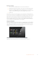
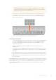
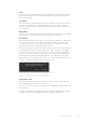

Table Of Contents
- English
- 日本語
- Français
- Deutsch
- Español
- 中文
- 한국어
- Русский
- Italiano
- Português
- Türkçe
- Getting Started
- Updating the Software
- Connecting to a Network
- Using ATEM Software Control
- Preference Settings
- Switcher Control Panel
- Media Manager
- Audio Mixer
- Camera Control
- Switcher Settings
- Using the Software Control Panel
- Processing Palettes
- Using the Audio Mixer
- Shaping your Audio Mix using Advanced Fairlight Controls
- Using the 6 Band Parametric Equalizer
- Fairlight Controls Workflow Guide
- Navigating the Browse Window on the Media Page
- ATEM Media Pool
- Changing Switcher Settings
- Setting Audio Input and Output Behavior
- Using Camera Control
- HyperDeck Control
- Using the ATEM Television Studio HD Front Panel
- Using ATEM Television Studio Pro Switchers
- Operating your ATEM Switcher
- Keying using ATEM Switchers
- Using Adobe Photoshop with ATEM
- Using the Auxiliary Output
- Using Macros
- Using External ATEM Hardware Panels
- Performing Transitions using ATEM Hardware Panels
- Using ATEM Camera Control Panel
- Using Tally
- Using Audio
- Developer Information
- Help
- Regulatory Notices
- Safety Information
- Warranty
- はじめに
- ソフトウェア・アップデート
- ネットワークに接続
- ATEM Software Controlの使用
- カメラコントロールの使用
- HyperDeckコントロール
- ATEM Television Studio HDフロントパネルの使用
- ATEM Television Studio Proスイッチャーの使用
- ATEMスイッチャーの操作
- ATEMスイッチャーのキーイング
- ATEMでAdobe Photoshopを使用する
- Aux出力のスイッチング
- マクロの使用
- 外付けATEMハードウェアパネルの使用
- ATEMハードウェアパネルを使ってトランジションを実行
- ATEM Camera ControlPanelの使用
- タリーの使用
- オーディオの使用
- Developer Information
- ヘルプ
- 規制に関する警告
- 安全情報
- 保証
- Mise en route
- Mettre à jour le logiciel
- Connexion à un réseau
- Utiliser l'ATEM Software Control
- Préférences
- Panneau de contrôle du mélangeur
- Gestionnaire de média
- Mixage audio
- Contrôle des caméras
- Paramètres du mélangeur
- Utiliser le panneau de contrôle logiciel
- Palettes de fonctions
- Utiliser le mixeur audio
- Réaliser le mixage audio à l’aide des commandes Fairlight avancées
- Exemple de workflow pour les commandes Fairlight
- Utilisation de la fenêtre de navigation sur la page Média
- Bibliothèque de média de l'ATEM
- Modification des paramètres du mélangeur
- Configurer le signal d’entrée et de sortie audio
- Utiliser la fonction de contrôle des caméras
- Contrôle de l'HyperDeck
- Utiliser le panneau avant de l'ATEM Television Studio HD
- Utiliser les mélangeurs ATEM Television Studio Pro
- Fonctionnement de votre mélangeur ATEM
- Incrustations avec les mélangeurs ATEM
- Utiliser Adobe Photoshop avec votre ATEM
- Utiliser la sortie auxiliaire
- Utiliser des macros
- Utiliser des panneaux matériels externes ATEM
- Effectuer des transitions avec les panneaux de contrôle matériels ATEM
- Utiliser l'ATEM Camera Control Panel
- Utiliser le tally
- Utiliser l'audio
- Developer Information
- Assistance
- Avertissements
- Informations de sécurité
- Garantie
- Erste Schritte
- Aktualisierung der Software
- Anschließen an ein Netzwerk
- Arbeiten mit ATEM Software Control
- Einstellungen
- Software-Bedienpanel des Mischers
- Media Manager
- Audiomixer
- Kamerasteuerung
- Mischereinstellungen
- Arbeiten mit dem Software-Bedienpanel
- Menüpaletten
- Arbeiten mit dem Audiomixer
- Gestalten Ihres Audiomixes mit erweiterten Fairlight Steuerelementen
- Arbeiten mit dem parametrischen 6-Band-Equalizer
- Dynamik-Steuerelemente
- Workflow-Anleitung zu den Fairlight Steuerelementen
- Navigieren im Browse-Fenster des Medien-Arbeitsraums
- ATEM Media Pool
- Ändern der Mischereinstellungen
- Einstellen des Ein- und Ausgabeverhaltens für Audio
- Arbeiten mit der Kamerasteuerung
- HyperDeck Steuerung
- Verwenden des ATEM Television Studio HD Front Panels
- Verwenden von ATEM Television Studio Pro Mischern
- Betrieb Ihres ATEM Mischers
- Keying auf ATEM Mischern
- Arbeiten mit Adobe Photoshop und ATEM Mischern
- Arbeiten mit dem Auxiliary-Ausgang
- Arbeiten mit Makros
- Arbeiten mit externen ATEM Hardware‑Bedienpulten
- Ausführen von Übergängen mit ATEM Hardware-Bedienpulten
- Arbeiten mit dem ATEM Camera Control Panel
- Arbeiten mit Tally
- Verwenden von Audio
- Developer Information (Englisch)
- Hilfe
- Gesetzliche Vorschriften
- Sicherheitshinweise
- Garantie
- Primeros pasos
- Actualizaciones
- Conexión a redes
- ATEM Software Control
- Configuración de preferencias
- Panel de control virtual
- Organización de contenidos
- Mezclador de audio
- Control de cámaras
- Ajustes del mezclador
- Uso del panel de control virtual
- Paneles de opciones
- Uso del mezclador de audio
- Configuración de la mezcla de audio mediante los controles avanzados de Fairlight
- Ecualizador paramétrico de seis bandas
- Dinámicas de trabajo con controles Fairlight
- Ventana de exploración en la pestaña Multimedia
- Panel multimedia
- Modificación de ajustes del mezclador
- Configuración de las entradas y salidas de audio
- Uso de la función de control de cámaras
- Herramientas de DaVinci Resolve para correcciones primarias
- DaVinci Resolve Micro Panel
- Control de grabadores HyperDeck
- Uso del panel frontal en el modelo ATEM Television Studio HD
- Uso de los modelos ATEM Television Studio Pro
- Botones para la señal principal y los anticipos
- Botones para transiciones
- Descripción general de los controles de audio
- Control de cámaras
- Controles del sistema de comunicación
- Uso de composiciones previas y posteriores
- Uso de los menús en pantalla
- Selección de fuentes para la salida auxiliar
- Fundido a negro
- Funcionamiento del mezclador
- Composición de imágenes
- Uso de Adobe Photoshop con mezcladores ATEM
- Uso de salidas auxiliares
- Macros
- Paneles de control ATEM
- Cómo realizar transiciones con los paneles ATEM
- Uso del dispositivo ATEM Camera Control Panel
- Sistemas de señalización
- Audio
- Información para desarrolladores
- Ayuda
- Normativas
- Seguridad
- Garantía
- 入门
- 更新软件
- 连接到网络
- 使用ATEM软件控制面板
- 使用摄影机控制
- HyperDeck控制
- 使用ATEM Television Studio HD前面板
- 使用ATEM Television Studio Pro切换台
- 操作ATEM切换台
- 使用ATEM切换台进行抠像
- Adobe Photoshop与ATEM切换台的配合使用
- 使用辅助输出
- 使用宏命令
- 使用外部ATEM硬件控制面板
- 使用ATEM硬件控制面板执行转场
- 使用ATEM Camera Control Panel
- 使用Tally
- 使用音频
- Developer Information
- 帮助
- 监管声明
- 安全信息
- 保修
- 시작하기
- 소프트웨어 업데이트
- 네트워크 연결
- ATEM Software Control 사용하기
- 카메라 컨트롤 사용하기
- HyperDeck 컨트롤
- ATEM Television Studio HD 전면 패널 사용하기
- ATEM Television Studio Pro 스위처 사용하기
- ATEM 스위처 작동하기
- ATEM 스위처에서 키잉하기
- ATEM에서 Adobe Photoshop 사용하기
- 보조 출력 사용
- 매크로 사용하기
- 외부 ATEM 하드웨어 패널 사용하기
- ATEM 하드웨어 패널에서 트랜지션 실행하기
- ATEM Camera Control Panel 사용하기
- 탈리 사용
- 오디오 사용
- 개발자 정보
- 지원
- 규제 사항 및 안전 정보
- 안전 정보
- 보증
- Подготовка к работе
- Обновление программного обеспечения
- Подключение к локальной сети
- Работа с ATEM Software Control
- Параметры
- Программная панель управления
- Управление медиаматериалами
- Звуковой блок
- Управление камерами
- Настройки видеомикшера
- Работа с программной панелью управления
- Секции обработки изображения
- Работа со звуковым блоком
- Обработка звука с помощью блока Fairlight
- Работа с шестиполосным параметрическим эквалайзером
- Работа с инструментами Fairlight
- Просмотр материалов на странице «Медиа»
- Библиотека мультимедиа на ATEM
- Изменение настроек видеомикшера
- Настройки ввода и вывода звука
- Использование функции управления камерами
- Управление рекордерами HyperDeck
- Работа с передней панелью ATEM Television Studio HD
- Работа с ATEM Television Studio Pro
- Работа с видеомикшером ATEM
- Кеинг с использованием видеомикшеров ATEM
- Использование Adobe Photoshop при работе с ATEM
- Подключение через дополнительный выход
- Работа с макрокомандами
- Работа с аппаратными панелями АТЕМ
- Выполнение переходов с помощью аппаратных панелей АТЕМ
- Работа с ATEM Camera Control Panel
- Индикация состояния
- Работа со звуком
- Информация для разработчиков
- Помощь
- Соблюдение нормативных требований
- Правила безопасности
- Гарантия
- Operazioni preliminari
- Aggiornare il software ATEM
- Connettersi a una rete
- Utilizzare ATEM Software Control
- Preferenze
- Struttura dell’interfaccia
- Multimedia
- Audio
- Camera
- Impostazioni dello switcher
- Utilizzare il pannello di controllo principale
- Menù di controllo
- Utilizzare il mixer audio
- Perfezionare il mix con i controlli avanzati Fairlight
- Utilizzare l’equalizzatore parametrico a 6 bande
- Esempio di flusso di lavoro Fairlight
- Navigare la libreria locale nella pagina Multimedia
- Archivio multimediale
- Cambiare le impostazioni dello switcher
- Impostare il funzionamento di ingressi e uscite audio
- Controllare le camere
- Controllare HyperDeck
- Utilizzare il pannello frontale di ATEM Television Studio HD
- Utilizzare gli switcher ATEM Television Studio Pro
- Operare lo switcher ATEM
- Utilizzare i keyer degli switcher ATEM
- Utilizzare Adobe Photoshop con ATEM
- Utilizzare l’uscita ausiliaria
- Utilizzare le macro
- Utilizzare i pannelli ATEM esterni
- Eseguire le transizioni con i pannelli ATEM esterni
- ATEM Camera Control Panel
- Utilizzare il tally
- Utilizzare l’audio
- Informazioni per gli sviluppatori
- Assistenza
- Normative
- Sicurezza
- Garanzia
- Instruções Preliminares
- Atualizar o Software
- Conectar a uma Rede
- Usar ATEM Software Control
- Ajuste das Preferências
- Painel de Controle do Switcher
- Gerenciador de Mídias
- Mixer de Áudio
- Controle de Câmera
- Configurações do Switcher
- Usar o Painel de Controle Virtual
- Paletas de Processamento
- Usar o Mixer de Áudio
- Produção de Áudio usando Controles Fairlight Avançados
- Usar Equalizador Paramétrico de 6 Bandas
- Guia de Fluxo de Trabalho dos Controles Fairlight
- Janela de Navegação na Página Mídia
- Pool de Mídia ATEM
- Alterar Configurações de Switcher
- Configurar Comportamento de Entrada e Saída de Áudio
- Usar Controle de Câmera
- Controle HyperDeck
- Usar o Painel Frontal do ATEM Television Studio HD
- Usar Switchers ATEM Television Studio Pro
- Operar Seu Switcher ATEM
- Chaveamento usando Switchers ATEM
- Usar Adobe Photoshop com ATEM
- Usar a Saída Auxiliar
- Usar Macros
- Usar Painéis Físicos ATEM Externos
- Executar Transições Usando Painéis ATEM Físicos
- Usar ATEM Camera Control Panel
- Usar Sinalização
- Usar Áudio
- Developer Information
- Ajuda
- Informações Regulatórias
- Informações de Segurança
- Garantia
- Başlarken
- Yazılımın Güncellenmesi
- Bir Ağa Bağlanma
- ATEM Software Control Kullanımı
- Tercih Ayarları
- Switcher Control Panel
- Medya Yöneticisi
- Ses Mikseri
- Camera Control (Kamera Kontrol)
- Switcher Ayarları
- Software Kontrol Panelinin Kullanımı
- İşleme Paletleri (Processing Palettes)
- Ses Mikserinin Kullanımı
- Gelişmiş Fairlight Kontrolleri ile Ses Miksinizi Geliştirme
- 6 Bant Parametrik Ekolayzer Kullanımı
- Fairlight Kontrolleri İş Akışı Kılavuzu
- Medya Sayfasında Tarayıcı Penceresini Yönlendirme
- ATEM Medya Havuzu
- Switcher Ayarlarının Değiştirilmesi
- Ses Giriş ve Çıkış Davranışının Ayarlanması
- Kamera Kontrolün Kullanımı
- HyperDeck Kontrol
- ATEM Television Studio HD Ön Panelin Kullanımı
- ATEM Television Studio Pro Switcher’lerin Kullanımı
- ATEM Switcher’inizin Kullanımı
- ATEM Switcher’leri Kullanarak Keyleme
- ATEM ile Adobe Photoshop Kullanımı
- Auxiliary Çıkışının Kullanımı
- Makroların Kullanımı
- Harici ATEM Donanım Panellerinin Kullanımı
- ATEM Donanım Panelleri kullanarak Geçişlerin Uygulanması
- ATEM Camera Control Panel’in Kullanımı
- Tally Kullanımı
- Ses Kullanımı
- Developer Information
- Yardım
- Mevzuata İlişkin Bildirimler
- Güvenlik Bilgileri
- Garanti

TIP The auxiliary output also carries camera control data so you can connect
the auxiliary output to a camera's program input if you want to. Camera control
signals are not sent via the multi view SDI output.
3 In your camera’s settings, set the camera ID number to match your switcher input.
For example, if studio camera 1 is connected to ‘cam 5’ on your ATEM switcher, the
camera number in your camera settings must also be set to 5. This ensures tally is
sent to the correct camera.
Connect a Blackmagic URSA Mini to any of your ATEM switcher’s SDI inputs,
and the corresponding SDI output back to the camera's program input
Connecting via Optical Fiber
1 Connect the Blackmagic Camera’s optical out/in to the optical out/in on an ATEMStudio
Converter or ATEM Talkback Converter 4K. You’ll need to have SMPTE compatible
optical fiber SFP modules installed in your Studio Camera and ATEM converter to
connect via optical fiber.
2 Connect a suitable SDI out from your ATEM converter to any SDI input on your
ATEM switcher.
3 Connect any one of your ATEM switcher’s SDI outputs, except the multi view outputs to
your ATEM Converter’s ‘SDI in’. Camera control signals are not sent via the multi view
SDI output.
4 On the Blackmagic camera, open the LCD menu and set the camera number to match
your switcher input. For example, if camera 5 is connected the 'cam 5' SDI input on your
ATEM switcher, your camera number must also be set to 5. This ensures tally is sent to
the correct camera.
Open ATEM Software Control preferences and set your switcher’s button mapping to make sure
you are switching the right camera with correct tally. With a video connection from your switcher
to a Blackmagic camera, you can also get the advantage of live tally indicators, as well as the
camera operators being able to view the program feed of your switcher by pressing the
camera’s ‘pgm’ button.
64Using Camera Control