Installation and Operation Manual Blackmagic MultiView June 2018 English, 日本語, Français, Deutsch, Español, 中文, 한국어, Русский, Italiano, Português and Türkçe.
English Welcome Thank you for purchasing Blackmagic MultiView! We hope you share our dream for the television industry to become truly creative by allowing anyone to have access to the highest quality video. By using MultiView 16 with today’s affordable Ultra HD televisions, you get the equivalent of up to 16 independent broadcast monitors.
Contents Blackmagic MultiView Getting Started 5 Plugging in Power 5 Connecting SDI Sources and Monitors 5 Setting your Multi View Layout 6 Connecting to a Network 8 Connecting Serial Control 8 Rack Installation 8 Using Multiple MultiViews 9 Changing Settings 9 Blackmagic MultiView 16’s Front Control Panel 10 Teranex Mini Smart Panel 15 Installing Teranex Mini Smart Panel 15 Teranex Mini Smart Panel Features 16 Control Buttons and Rotary Knob 16 Changing Settings using Teranex Min
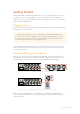
Getting Started Getting started with your Blackmagic MultiView is as easy as plugging in power, connecting your SDI video sources, and plugging your monitors and televisions into the HDMI or SDI outputs. This section of the manual will show you everything you need to know to get started using your Blackmagic MultiView. Plugging in Power To power your Blackmagic MultiView, simply plug a standard IEC power cord into the 110-240V AC power input on the rear panel.
TIP On Blackmagic MultiView 16 you can output the multi view via dedicated HD-SDI outputs, or up to Ultra HD via the 6G-SDI and HDMI outputs. Blackmagic MultiView 4 and MultiView 16 has loop outputs above each input so you can also connect each source to other video equipment.
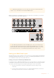
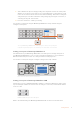
16 3 2 3 4 5 4 Select 4x4 from the layout setting by turning the rotary knob on the front control panel. 4x4 lets you see all 16 source views on one screen. Whenever a setting changes, you’ll notice the ‘set’ button and the ‘menu’ button will start flashing. This means a setting has changed and you can either confirm the setting change by pressing the ‘set’ button, or cancel by pressing the ‘menu’ button. LOOP OUT Press the set button to confirm your setting.
Connecting to a Network Your Blackmagic MultiView supports the Blackmagic Videohub Ethernet Protocol so if your unit is installed in a rack with limited access, you can easily control it remotely using a Blackmagic Videohub control panel, such as Blackmagic Smart Control and Master Control. Once connected to your network via Ethernet, your Blackmagic MultiView will be visible to other computers and Videohub panels connected to the network. These devices can then control the unit remotely.
Using Multiple MultiViews You can use multiple BlackMagic MultiViews in combination to create custom monitoring setups. This is helpful if you need to add more view sources to your multi view output. Simply plug the output from one MultiView into the input of another to add more source views to your multi view output. It is highly recommend that the upstream multi view output is connected to an Ultra HD monitor for maximum clarity.
Videohub Control software – When your Blackmagic MultiView 16 or Blackmagic MultiView 4 is connected to a network, you can use Blackmagic Videohub Control software to route sources, change views, and select the audio input source. Refer to the ‘Using Videohub Software Control’ section for more information. Blackmagic MultiView 16’s Front Control Panel Blackmagic MultiView 16’s front control panel makes it very easy to change any of the settings.
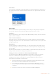
Solo Button You can monitor a view in full screen by pressing the ‘solo’ button. Now press any view button on the control panel to monitor that view in full screen mode. Press solo again to return to the multi view layout. The solo feature lets you monitor a view in full screen mode Menu Button Press the ‘menu’ button to open the settings screen. Change a setting using the rotary knob and set button, then press the menu button again to return to the ‘home’ screen.
16 LOOP OUT 2 3 4 5 4 6 5 Press the ‘set’ button to confirm your setting. Press a numbered view button on the control panel to select your desired input. IN Alternatively, you can use the rotary knob to scroll through your inputs on the LCD.
Highlight the menu item you with to adjust and press “set” to open its settings You can choose from 3 different multi view layouts to best suit the number of inputs you have connected Audio In This setting is used to select the SDI input from which audio will be taken and embedded into the multi view outputs. Overlay This submenu lets you change the appearance of your multi view by turning overlay features on or off. Overlay features are: Borders – Lets you separate each view in a grid like pattern.
For tally to work properly, make sure you connect your Blackmagic MultiView 16’s inputs so they match the input numbers on your ATEM switcher or tally may be displayed on the wrong view. Video Out The ‘video out’ settings let you control output options on your Blackmagic MultiView 16. Video Format – Use this setting to change your Ultra HD multi view output frame rate to 2160p29.97 or 2160p25. The HD multi view output frame rate will conform to the Ultra HD output.
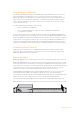
Use the rotary knob or the view buttons on Blackmagic MultiView 16’s control panel to assign values to your network settings Teranex Mini Smart Panel The Teranex Mini Smart Panel mounts to the front of your Blackmagic MultiView 4 and replaces the original basic panel. You get fast access to your settings using buttons, a rotary knob and built in LCD.
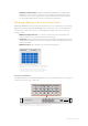
1 MENU 2 VIDEO SET AUDIO When installing the Teranex Mini Smart Panel to your Blackmagic MultiView 4, holding the panel with your fingers and thumb aligned with the panel’s rear connector will help guide it into place TIP The original basic panel is very strong, so if you need to mount your Blackmagic MultiView 4 in the back of a rack system or in areas where there are lots of cables or activity, you can always reinstall the original basic panel.
1 and 2 buttons – Press these buttons to increase or decrease numeric setting values, or to move up or down through menu settings. Set – After changing a setting using the 1 and 2 buttons, press the ‘set’ button to confirm your setting. Menu – Press to enter the settings menu for your Blackmagic MultiView 4. You can also press the menu button to step back through menu items all the way to the home screen.
Video Format Your Blackmagic MultiView 4 can be set to Ultra HD or HD output at either 29.97 or 25 frames per second. Use this setting to cycle through the available resolution and frame rate options. Overlay The overlay submenu lets you set the appearance of overlay features on or off. Overlay features are: Borders – Lets you separate each view in a grid like pattern. Labels – Makes ‘view’ labels visible or hidden. Labels can be changed using Blackmagic MultiView Setup.
Changing Settings using Switches On Blackmagic MultiView 4 and MultiView 4 HD, there are small built in switches to let you change settings. On the Blackmagic MultiView 4, the switches are on the front panel, behind a rubber dust cap. On Blackmagic MultiView 4 HD, the switches are on the side of the unit.
Switch Settings for Blackmagic MultiView 4 Blackmagic MultiView 4 AUDIO SOURCE INPUT 1 8 AUDIO SELECTION BIT 1 INPUT 2 7 AUDIO SELECTION BIT 0 INPUT 3 6 LABELS OFF LABELS ON 5 AUDIO METERS OFF AUDIO METERS ON 4 BORDER OFF BORDER ON INPUT 4 SDI OUTPUT 2160p29.97 3 2160p25 2 SDI OUTPUT BIT 1 1 SDI OUTPUT BIT 0 1080i59.
Switch 2 and 1 Switches 2 and 1 are represented as bits 1 and 0 respectively. This means that by setting various on/off combinations of switches 2 and 1 you can select the output format of your MultiView 4’s SDI signal. SDI Output Selection Table SDI Output Switch 2 Switch 1 2160p29.97 ON ON 2160p25 ON OFF 1080i59.94 OFF ON 1080i50 OFF OFF Switch Diagram NOTE When using the optional Teranex Mini Smart Panel, the switch settings will be overridden by the Smart Panel settings.
Blackmagic MultiView 4 HD’s switches let you change the following settings: Switch 8 and 7 – SDI Audio Embed and Solo Select Switches 8 and 7 are grouped together to provide 4 ON/OFF combinations. Having four different combinations allows the audio from any one of the four SDI inputs to be embedded into the multi view output. In solo mode, audio follows video, so you can use these switches to select the view source and audio source.
Using Blackmagic MultiView Setup Blackmagic MultiView Setup lets you easily configure your Blackmagic MultiView from any Mac or Windows PC, as well as update the unit’s internal software. The utility is intuitive and easy to use, plus if you have Blackmagic MultiView 4 connected to a network, you can even change settings via Ethernet so you don’t have to plug in via USB.
Mac OS X installation 1 Double click the installer file from the supplied media or from your downloads folder if you downloaded the software from the Blackmagic Design website. 2 Follow the install prompts and Mac OS X will automatically install the software. A folder called “Blackmagic MultiView” will be created within your applications folder, containing the Blackmagic MultiView Setup application.
Use Blackmagic MultiView Setup to customize input labels so you can quickly identify each source within the multi view layout Sources – Lets you customize your input labels. This changes how your sources are labelled on your multi view display. Views – This tab is only relevant when controlling Blackmagic MultiView 16 via Videohub Control software. By changing the name of the views, you can make them easier to identify within the destinations panel in the Videohub Control software.
Views Customizing View Labels On Blackmagic MultiView 16, you can change the labels of the views so they are easier to identify as destinations when controlling your MultiView 16 via Videohub Control software. To customize the view labels: 1 Click on the ‘views’ tab. 2 In the ‘output labels’ setting, click the text box for the view you want to change and enter a new label name. 3 Click ‘save’ to confirm your setting.
Video Output Video Format and HD Output Video format settings differ slightly between Blackmagic MultiView models. Blackmagic MultiView 16 can output HD and Ultra HD video simultaneously. You can also choose the video frame rate you want to output. For example if you want to output a signal that conforms to the format commonly used in the USA, select 2160p29.97 and the HD output will automatically match the frame rate. In this example, if 2160p29.
Changing the Multi View Layout Similar to the ‘layout’ settings on Blackmagic MultiView 16’s control panel LCD menu, you can also change the layout using the setup software. Choose the layout setting you wish to use by clicking on the desired layout icon in the ‘details’ settings. Set the screen layout for MultiView 16 in the ‘video output’ tab.
TIP ‘Tally override’ mode works with Blackmagic URSA Mini, URSA Mini 4K, URSA Mini Pro, and URSA Broadcast cameras that are connected to a Blackmagic ATEM switcher or Blackmagic Camera Fiber Converter. For information on how to connect a third party switcher or third party tally, refer to the Blackmagic 3G-SDI Shield for Arduino manual. SD Aspect Ratio If 4:3 SD video is connected to your Blackmagic MultiView, check the ‘set to 4:3’ checkbox.
On Blackmagic MultiView 16 and Blackmagic MultiView 4, the overlay settings in the ‘configure’ tab lets you turn overlay features on or off such as borders, view labels, audio meters, or even SDI tally borders TIP For tally to work properly, make sure you connect all your Blackmagic MultiView inputs so they match the input numbers on your ATEM switcher or tally may be displayed on the wrong view. Configure Naming your Blackmagic MultiView The ‘Configure’ tab differs between Blackmagic MultiView models.
Network and Serial Control Settings Network and serial control settings can be set using Blackmagic MultiView Setup when your Blackmagic MultiView 16 is connected to your computer via USB. You can also change these settings using the front control panel LCD menu. When configuring Blackmagic MultiView 4, only network settings are available. To change network settings, simply click in the text box and enter the values with your keyboard, or check the desired checkbox.
Use Blackmagic MultiView setup to save and load labels Updating the Internal Software Occasionally, the internal software in your Blackmagic MultiView will need to be updated. Updates to internal software can provide new features, compatibility with new hardware, and support for new formats. To update your Blackmagic MultiView internal software: 1 Connect your Blackmagic MultiView to your computer via USB or Ethernet.
Using Videohub Control Software When you have Blackmagic MultiView 16 connected to a network, you can use Blackmagic Videohub Control on a Mac or Windows computer to route Blackmagic MultiView 16’s video inputs to different views within your multi view layout. Your Blackmagic MultiView’s SDI inputs appear as pushbuttons within the ‘sources’ panel, while the views appear as pushbuttons within the ‘destinations’ panel.
Viewing your Inputs To see which of your Blackmagic MultiView 16’s video inputs is routed to a particular view, click a view pushbutton in the destinations panel. The destination, or view, button will illuminate. In the ‘sources’ panel, the pushbutton of the routed video input will also illuminate, making it clear which input, or source, is routed to the view.
Developer Information Blackmagic Videohub Ethernet Protocol v2.3 Summary Your Blackmagic MultiView is compatible with the Blackmagic Videohub Ethernet Protocol. It is text based and is accessed by connecting to your Blackmagic MultiView’s IP address and TCP port 9990. NOTE Controlling your MultiView via Ethernet is available on Blackmagic MultiView 16 and Blackmagic MultiView 4, however, most features are relevant to Blackmagic MultiView 16.
This example is for the Blackmagic MultiView 16 which has 16 sources and 18 views including solo which is view 16 and audio which is view 17, referred to here as outputs. Legend ↵ line feed … and so on Version 2.3 of the Blackmagic Videohub Ethernet Protocol was released with Videohub 4.9.1 software Initial Status Dump The next two blocks enumerate the labels assigned to the input and output ports.
Status Updates When any route, label, or lock is changed on the multi view by any client, the multi view resends the applicable status block, containing only the items that have changed. If multiple items are changed, multiple items may be present in the update: OUTPUT LABELS:↵ 7 New output 8 label↵ 10 New output 11 label↵ ↵ Requesting Changes To update a label, lock or route, the client should send a block of the same form the multi view sends when its status changes.
In the absence of simultaneous updates, the dialog expected for a simple label change is as follows: OUTPUT LABELS:↵ 6 new output label seven↵ ↵ ACK↵ ↵ OUTPUT LABELS:↵ 6 new output label seven↵ ↵ The asynchronous nature of the responses means that a client should never rely on the desired update actually occurring and must simply watch for status updates from the MultiView and use only these to update its local representation of the server state.
The RS-422 serial port is configured as 9600 N81: 9600 is the line speed, or baud rate, at 9600 bits/sec. N represents no parity check, or ‘none’. 8 is the data length. 1 is for stop bits. To summarize N81, data without a parity check begins with 1 start bit, includes 8 true data bits, and 1 stop bit. There are 10 bits in total. The protocol is line oriented, with a maximum length of 250 characters per command. Each command from the client should be terminated with a carriage return (\r).
Pin No. Function Pin 1 TX + Pin 2 TX - Pin 3 GND Pin 4 GND Pin 5 RX - Pin 6 RX + Pinout diagram for the RJ11 connector Notifications Once connected, if status reporting is enabled, the client will receive a notification message when a route changes on the MultiView. The notifications take one of two forms: S:0destination,source Routing change This message indicates that the specified source port is now routed to the specified destination.
Salvo Commands @ P:0/destination,source queue route change @ P:0/destination,source/destination-2,source-2… queue multiple route changes The specified routing changes are added to the current salvo for later execution. request individual port status in salvo If a routing change for the specified destination port is queued, the route will be returned as a V: notification.
Help Getting Help The fastest way to obtain help is to go to the Blackmagic Design online support pages and check the latest support material available for your Blackmagic MultiView. Blackmagic Design Online Support Pages The latest manual, software and support notes can be found at the Blackmagic Design support center at www.blackmagicdesign.com/support. Blackmagic Design Forum The Blackmagic Design forum on our website is a helpful resource you can visit for more information and creative ideas.
Regulatory Notices and Safety Information Regulatory Notices Disposal of waste of electrical and electronic equipment within the European union. The symbol on the product indicates that this equipment must not be disposed of with other waste materials. In order to dispose of your waste equipment, it must be handed over to a designated collection point for recycling.
Warranty Limited Warranty Blackmagic Design warrants that Blackmagic MultiView will be free from defects in materials and workmanship for a period of 36 months from the date of purchase excluding connectors, cables, cooling fans, fiber optic modules, fuses, keyboards and batteries which will be free from defects in materials and workmanship for a period of 12 months from the date of purchase.