Installation and Operation Manual Blackmagic Studio Cameras September 2018 English, 日本語, Français, Deutsch, Español, 中文, 한국어, Русский, Italiano, Português and Türkçe.
Languages To go directly to your preferred language, simply click on the hyperlinks listed in the contents below.
English Welcome Thank you for purchasing a Blackmagic Studio Camera! We are extremely excited to have designed the Blackmagic Studio Camera and Micro Studio Camera 4K. Ever since I was a teenager I have loved live production, it’s so exciting! Traditionally cameras with talkback and tally were very expensive and physically large, so hard to manage.
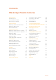
Contents Blackmagic Studio Cameras Getting Started 5 Connecting to Video Switchers 29 Attaching a Lens 5 Connecting to Recorders 30 Turning Your Camera On 5 Remote Record 30 Connecting to a switcher 6 RAW SDI Output 30 Camera Features 8 Connecting Tally using the Blackmagic 3G-SDI Shield for Arduino 31 Blackmagic Studio Camera Features 8 Blackmagic Micro Studio Camera 4K Features 10 Blackmagic Camera Setup 33 Camera Connections 13 Sun Shade 34 Blackmagic Studio
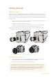
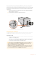
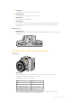
Getting Started Attaching a Lens Getting started with your Blackmagic Studio Camera or Blackmagic Micro Studio Camera 4K is as simple as attaching a lens and turning the camera on. To remove the protective dust cap from the lens mount, hold down the locking button and rotate the cap counterclockwise until it is released. We recommend you always turn off your Blackmagic camera prior to attaching or removing a lens. To attach a lens: 1 Align the dot on your lens with the dot on the camera mount.
Micro Studio Camera 4K accepts LP-E6 and LP-E6N batteries, which can be charged with an external battery charger or slowly trickle charged by the camera. The camera can also be charged and operated via external power and will switch between power sources automatically if external power is interrupted. External power is provided via the Micro Studio Camera 4K’s expansion port. 1 Press the power button on the right hand side of the camera. The tally light will glow white to indicate the camera is on.
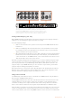
IN 3 IN 1 CONTROL USB 2.0 IN 1 HDMI IN IN 2 CONTROL IN 4 USB 2.0 IN 1 IN 5 IN 1 IN 7 IN 3 IN 9 IN 5 IN 7 1 IN 6 IN 2 IN 8 IN 4 IN 10 IN 6 IN 8 2 HDMI IN IN 9 3 1 1 3 REMOTE REMOTE 1 PUSH STEREO IN IN 10 2 2 2 HD HD HD HD HD HD CH 1 SDI INPUTS SDI INPUTS CONTROL USB 2.
Connecting to a Recorder You can also connect your Blackmagic Studio Camera to an external recorder, for example a Blackmagic HyperDeck Studio disk recorder for indoor studio recording. Or even mount a HyperDeck Shuttle or Blackmagic Video Assist to your studio camera and loop through to the switcher for ISO recordings during an outside broadcast. That’s all there is to getting started! Live production is exciting and your Blackmagic Studio Camera is designed to give you an easy and fun experience.
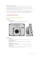
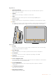
Right Panel 6 Optical Input/Output Optical input and output allows cable runs of up to 28 miles when the optional SFP optical module is fitted. 7 SDI Out SDI output for connecting to a switcher or other device. 8 SDI In SDI input allows the camera operator to view the Program (PGM) output. 9 Reference Input Allows multiple cameras to be genlocked to a blackburst or tri-level reference signal. 10 Power 12 – 24V power input for power supply and battery charging, where applicable.
12V REF 19 Set Button Use this button to confirm your menu selections. SDI IN SDI OUT 20 Display Button Press this button to toggle overlays on and off. OPTICAL IN OPTICAL OUT 21 Menu Button Access the menu on the LCD. 22 Power Button Press the power button to turn on the Blackmagic Studio Camera. Press and hold the button to turn the camera off. Refer to the ‘button settings’ section in this manual for more details. Bottom Panel 23 USB Connector USB Mini-B port for camera firmware updates.
Left Panel 2 4 5 6 3 7 8 2 HDMI Out The HDMI output lets you preview your video output and navigate the camera menus using external monitors such as Blackmagic Video Assist. Output resolution is always 1080HD, unless you have 720p selected, in which case the output resolution will also be 720p. You can choose to display overlays such as frame guides, a histogram, and audio levels. See the ‘monitoring settings’ section in this manual for more details. 3 Expansion Port DB-HD15 connector.
11 SDI In SDI input allows camera control via ATEM switchers or the Blackmagic 3G-SDI Shield for Arduino. 12 Headphone / Talkback 3.5mm jack for talkback with iPhone and Android style headsets. Double press the play/pause button on your headset to toggle talkback on and press it once again to turn talkback off. Rear Panel 13 13 Battery Slot Blackmagic Micro Studio Camera 4K comes with one LP-E6 battery which fits into this slot.
Camera Connections Blackmagic Studio Camera – Left Side 2 3 PUSH 1 1 2 3 PUSH 1 2 LANC Remote Control The remote port on your camera is used to remotely control lens focus, iris and zoom adjustments when using a compatible lens. The port takes a 2.5 mm stereo jack using the standard LANC protocol. Active MFT lenses allow you to control the zoom servo with a LANC controller. The following lenses are currently supported: Panasonic Lumix G X Vario PZ 14-42mm f/3.5-5.6 Power O.I.S.
Blackmagic Studio Camera – Right Side OPTICAL OUT OPTICAL IN SDI OUT SDI IN REF 12V Optical Input/Output For optical fiber input and output, you will need to install an optional optical fiber SFP module. This lets you connect industry standard LC connectors, supporting 3G-SDI on Studio Camera HD, and 6G-SDI on Studio Camera 4K. Optical fiber cable is widely available because it’s the same cable used in computer networking.
Power Use the 12 - 24V power input for connecting your power supply and to charge the internal battery in Blackmagic Studio Camera HD and Blackmagic Studio Camera 4K. When the battery in these cameras is charged it will power the camera for up to 4 hours on Studio Camera HD, and up to 3 hours on Studio Camera 4K. Blackmagic Studio Camera 2 and Studio Camera 4K 2 do not have internal batteries.
Blackmagic Micro Studio Camera 4K – Right Side Analog Audio In The 3.5mm stereo audio connector accepts microphone or line level audio. You can switch between these options in the camera’s ‘audio settings’ menu. It’s important to select the appropriate setting or your audio may sound too quiet or too loud. SDI Out Use the SDI out connector to output 10-bit 4:2:2 video to professional SDI video equipment such as routers, monitors, SDI capture devices and broadcast switchers.
Customization Blackmagic Micro Studio Camera 4K Expansion Cable There are two ways to access the expansion port’s functions. You can use the expansion cable that comes with your Micro Studio Camera 4K, or solder your own custom connectors. The expansion cable provides connectors for the following control options. 1 2 3 Micro Studio Cam MSC Breakout Cable Micro Studio Cam MSC Breakout Cable 4 5 6 Blackmagic Micro Studio Camera 4K expansion cable.
You can adjust settings such as iris, focus and zoom in the same way you would an active MFT lens, either via an ATEM switcher using the ‘camera control’ page, or via other remote control interfaces that can be connected to the Micro Studio Camera 4K expansion cable. For a list of supported B4 digital lenses, refer to the Blackmagic Design support center at www.blackmagicdesign.com/support/faq/59011 6 S.Bus Digital Servo By connecting to a compatible S.Bus receiver using the Futaba J cable, you have 17 S.
Settings You can change settings on your Blackmagic camera to get the best picture, such as video format, shutter speed and white balance, plus you can adjust audio levels, monitoring settings, and studio tally and talkback settings for effective communication with the control room. This section of the manual contains detailed information on each of the settings in your camera.
Auto Exposure Blackmagic Micro Studio Camera 4K gives you several auto exposure options. Iris Maintains a constant shutter speed while changing the aperture to achieve a constant exposure. Shutter Maintains a constant aperture while changing the shutter speed to achieve a constant exposure. Iris + Shutter Mantains the correct exposure levels by adjusting the aperture.
Blackmagic Studio Camera Blackmagic Studio Camera 4K Blackmagic Micro Studio Camera 4K 1080p30 1080p30 1080p30 1080p50 1080p50 1080p50 1080p59.94 1080p59.94 1080p59.94 1080p60 1080p60 1080p60 – 2160p23.98 2160p23.98 – 2160p24 2160p24 – 2160p25 2160p25 – 2160p29.97 2160p29.97 – 2160p30 2160p30 – 2160p50 – – 2160p59.
Microphone Level Microphone input adjusts the recording levels of the built in microphone. Move the audio slider left or right to increase or decrease levels. Studio Camera has a built in stereo microphone. The built in microphone records to audio channels 1 and 2 when no external audio source is connected. Input Level External audio connectors support audio at microphone level or line level. Select Line when connecting external audio equipment such as an audio mixer or amplifier.
This setting toggles the histogram on and off. When on, this will appear in the bottom right corner of an attached monitor when ‘HDMI overlays’ are set to on. Monitoring settings - Blackmagic Micro Studio Camera 4K. Audio The audio meter represents the current volume of left and right audio channels in two horizontal bars. Left is on top, right is on the bottom. If your audio levels rise too high, your audio peaks can be clipped and you will hear distortion in your audio.
Rear Tally Brightness Changes the brightness of the rear tally light. Settings include: low, medium and high. The default setting is medium. Tally Light Brightness Changes the brightness of the tally light on Micro Studio Camera 4K. The default setting is medium but you can also set it to high, low or off. If you have set the tally brightness to ‘off’, the tally light will illuminate when your camera is powered on, and then will turn off shortly afterwards.
TIP You can also connect the program return feed from any SDI switcher to your camera via a Blackmagic 3G-SDI Shield for Arduino and display tally on each camera. All SDI switchers that have open collector tally outputs are configurable for tally using the Blackmagic 3G-SDI Shield for Arduino. Refer to the section titled ‘Connecting tally using the Blackmagic 3G-SDI Shield for Arduino’ for more information. Reference Source Used to select the genlock source.
Assigning Camera Functions to S.Bus Channels If you are using S.Bus to control your Blackmagic Micro Studio Camera 4K, you can use the ‘remote’ menu to assign the following functions to individual S.Bus channels: Trigger record Iris Focus Auto focus Zoom Gain Shutter speed White balance Audio levels Frame rate To assign functions to individual S.Bus channels, simply select the function you wish to control and assign an available channel using the ‘up,’ ‘down’ and ‘set’ buttons.
You could assign camera functions to a control like a spring loaded joystick which snaps back to a neutral center point after each movement up or down. In this example a value of 44 would represent the maximum downward position of the joystick and 212 would represent the maximum upward position, while the center functions as a neutral point with a value of 128.
Iris Button When using video dynamic range settings, a single press of the iris button will set an average exposure based on the highlights and shadows in your shot. When using film dynamic range settings, pressing the iris button sets your exposure to accommodate the brightest highlight in your shot. To set your aperture manually on your Studio camera, press the up and down menu navigation buttons.
Display Button Press this button to display useful information on your Studio Camera’s 10” monitor, including: Frame guides with camera and lens settings such as camera number, video format and frame rate, shutter speed, white balance, battery life, gain setting and f-stop number. Press the Disp button again to turn overlays off and monitor the image only. Overlays are visible on the 10” monitor. The SDI output is always clean.
Connecting to Recorders If you simply wish to record your Studio Camera’s output, you can connect the SDI output to the SDI input of an SSD recorder such as the Blackmagic HyperDeck Shuttle. The SDI output from the HyperDeck can then be connected to the Studio Camera’s SDI input, so you can view your recordings on the camera’s LCD.
Connecting Tally using the Blackmagic 3G-SDI Shield for Arduino If you are using an SDI switcher with a tally output connector, you can connect the tally outputs to a Blackmagic 3G-SDI Shield for Arduino to send tally signals to your Blackmagic Studio Cameras. This means you can still get tally on your Blackmagic cameras via the SDI program return feed even if you aren’t using an ATEM switcher.
The example sketch above shows how the Blackmagic 3G-SDI Shield for Arduino is programmed to detect a tally signal for input 1 or 2 via the switcher’s tally output, and then embed that tally signal into the shield’s SDI output. The tally light on the corresponding camera will then illuminate.
Blackmagic Camera Setup How to Update Your Camera Software on Mac OS X After downloading the ‘Blackmagic Camera Setup’ software, unzip the downloaded file and double click on the .dmg disk image file. Launch the ‘Blackmagic Camera Setup’ installer and follow the onscreen instructions. Blackmagic Camera Setup software.
The Mini-B USB 2.0 ports are located on the underside of the cameras. Attaching Accessories Sun Shade The Studio Cameras include a foldable sun shade to shade the LCD in bright conditions and ensure optimum viewing is possible at all times. 1 Locate the 6 thumbscrews that are included with your Studio Camera. 2 Align the holes in the sun shade with the camera’s mounting points and screw in 2 thumbscrews to the top and each side of the camera to firmly secure the sun shade.
Using ATEM Software Control Introducing Camera Control Your Blackmagic Studio Camera can be controlled from an ATEM switcher using the Camera Control feature in ATEM Software Control. Clicking on the Camera button opens the camera control feature. Settings such as iris, gain, focus and zoom control are easily adjusted using compatible lenses, plus you can color balance cameras and create unique looks using the DaVinci Resolve primary color corrector.
CONTROL USB 2.0 IN 1 CONTROL IN 2 HDMI IN IN 4 IN 1 USB 2.0 IN 5 IN 1 IN 7 IN 3 IN 9 IN 5 IN 7 1 IN 6 IN 2 IN 8 IN 4 IN 10 IN 6 IN 8 2 HDMI IN IN 9 3 1 1 3 REMOTE REMOTE 1 PUSH STEREO IN IN 10 2 2 2 HD HD HD HD HD IN 1 USB 2.
Using Camera Control Launch ATEM Software Control and click on the Camera button located at the bottom of the software window. You’ll see a row of labeled camera controllers containing tools to adjust and refine each camera’s image. The controllers are easy to use. Simply click the buttons using your mouse, or click and drag to adjust. Camera Control Selection The button row at the top of the camera control page lets you select the camera number you would like to control.
Show/Hide Color Bars Blackmagic cameras have a color bars feature built in which you can turn on or off by selecting ‘show’ or ‘hide’ color bars. This feature can be very useful for visually identifying individual cameras while setting up for your live production. Color bars also provide an audio tone so you can easily check and set the audio levels from each camera. Detail Use this setting to sharpen the image from your cameras live.
Iris/Pedestal Control The iris/pedestal control is located within the cross hairs of each camera controller. The control illuminates red when its camera is on air. To open or close the iris, drag the control up or down. Holding the shift key allows only iris adjustments. To darken or lift the pedestal, drag the control left or right. Holding the command key on a Mac, or the Control key on Windows, allows only pedestal adjustments.
Auto Focus Button The auto focus button is located at the bottom left corner of each camera controller. Press to automatically set the focus when you have an active lens that supports electronic focus adjustments. It’s important to know that while most lenses support electronic focus, some lenses can be set to manual or auto focus modes, and so you need to ensure your lens is set to auto focus mode. Sometimes this is set by sliding the focus ring on the lens forward or backward.
Hovering your mouse pointer over the gain, shutter speed and white balance indicators reveal arrows you can click on to adjust their respective settings. DaVinci Resolve Primary Color Corrector If you have a color correction background, then you can change the camera control from a switcher style CCU interface to a user interface that’s more like a primary color corrector on a post production color grading system.
Use the color wheels in the following ways to make fine or aggressive adjustments: Click and drag anywhere within the color ring: Note that you don’t need to drag the color balance indicator itself. As the color balance indicator moves, the RGB parameters underneath change to reflect the adjustments being made to each channel. Shift-Click and drag within the color ring: Jumps the color balance indicator to the absolute position of the pointer, letting you make faster and more extreme adjustments.
Saturation Setting The Saturation setting increases or decreases the amount of color in the image. The default setting is 50%. Hue Setting The Hue setting rotates all hues of the image around the full perimeter of the color wheel. The default setting of 180 degrees shows the original distribution of hues. Raising or lowering this value rotates all hues forward or backward along the hue distribution as seen on a color wheel.
The commands that the Micro Studio Camera 4K can accept over SDI are: Lens Zoom Lens Focus Lens Iris Pan Tilt Memory Set Memory Recall Memory Reset These commands are referenced in the ‘Blackmagic SDI Control Protocol’ section in this manual. Most PTZ heads support the setting and recalling of their positions but it is a good idea to check which commands are supported by each PTZ head manufacturer.
PTZ with Blackmagic 3G-SDI Shield for Arduino Using the Blackmagic 3G-SDI Shield with an Arduino board, a joystick and a switch, you can control a PTZ head via Blackmagic Micro Studio Camera 4K. To connect Blackmagic Micro Studio Camera 4K to the Blackmagic Design 3G-SDI shield 1 Connect the Blackmagic Design 3G-SDI shield to an Arduino board. 2 Connect your custom shield to the Arduino board.
Controlling your Arduino The following sketch demonstrates a simple example of using a joystick and button with an Arduino board and the Blackmagic 3G-SDI Shield for Arduino, to control a PTZ head via a Blackmagic Micro Studio Camera 4K.
PTZ Control over SDI 47
Developer Information Blackmagic SDI Camera Control Protocol Version 1.3 If you are a software developer you can use the SDI Camera Control Protocol to construct devices that integrate with our products.
Command id (uint8) The command id is an 8 bit unsigned integer which indicates the message type being sent. Receiving devices should ignore any commands that they do not understand. Commands 0 through 127 are reserved for commands that apply to multiple types of devices. Commands 128 through 255 are device specific. Reserved (uint8) This byte is reserved for alignment and expansion purposes. It should be set to zero. Command data (uint8[]) The command data may contain between 0 and 60 bytes of data.
Data types 129 through 255 are available for device specific purposes. Operation type (uint8) The operation type specifies what action to perform on the specified parameter. Currently defined values are: 0: assign value The supplied values are assigned to the specified parameter. Each element will be clamped according to its valid range. A void parameter may only be 'assigned' an empty list of boolean type. This operation will trigger the action associated with that parameter.
Group ID 1.0 Video Parameter Video mode 1.1 Gain 1.2 Manual White Balance 1.
Group ID Parameter Type Index Minimum Maximum Interpretation 2.0 Mic level fixed16 – 0 1 0.0 = minimum, 1.0 = maximum 2.1 Headphone level fixed16 – 0 1 0.0 = minimum, 1.0 = maximum 2.2 Headphone program mix fixed16 – 0 1 0.0 = minimum, 1.0 = maximum 2.3 Speaker level fixed16 – 0 1 0.0 = minimum, 1.0 = maximum 2.4 Input type int8 – 0 2 0 = internal mic, 1 = line level input, 2 = low mic level input, 3 = high mic level input [0] ch0 0 1 0.0 = minimum, 1.
Group ID Parameter Type Index Minimum Maximum Interpretation 4.0 Brightness fixed16 – 0 1 0.0 = minimum, 1.0 = maximum – – – 0x4 = zebra Overlay enables int16 bit field – – – 0x8 = peaking – – – 4.1 Display 4.2 Zebra level fixed16 – 0 1 0.0 = minimum, 1.0 = maximum 4.3 Peaking level fixed16 – 0 1 0.0 = minimum, 1.0 = maximum 4.
Group ID 8.0 8.1 8.2 Parameter Lift Adjust Gamma Adjust Gain Adjust Type fixed16 fixed16 fixed16 Color Correction 8.3 Offset Adjust fixed16 8.4 Contrast Adjust fixed16 8.5 Luma mix fixed16 8.6 Color Adjust fixed16 8.7 Correction Reset Default void Index Minimum Maximum Interpretation [0] red -2 2 default 0.0 [1] green -2 2 default 0.0 [2] blue -2 2 default 0.0 [3] luma -2 2 default 0.0 [0] red -4 4 default 0.0 [1] green -4 4 default 0.
Group ID Parameter Type Index [0] = basic codec 10.
Example Protocol Packets Operation Packet Length Byte 0 1 2 8 9 10 11 1 0 0 0 12 13 14 15 0 0 0 0 0 0 0 0 parameter type operation data category command 7 reserved turn on OIS on all cameras 6 command auto focus on camera 4 5 length trigger instantaneous 4 destination header 3 8 4 4 0 0 0 1 0 0 12 255 5 0 0 0 6 0 0 12 4 8 0 0 1 5 3 0 0x10 0x27 0x00 0x00 12 4 6 0 0 4 2 128 1 0x33 0x01 16 255 9 0 0 1 0 1 0 24 1 16 4
Blackmagic Embedded Tally Control Protocol Version 1.0 (30/04/14) This section is for third party developers or anybody who may wish to add support for the Blackmagic Embedded Tally Control Protocol to their products or system. It describes the protocol for sending tally information embedded in the non-active picture region of a digital video stream.
uint8[1] bit 0: bit 1: bit 2-3: bit 4: bit 5: bit 6-7: ...
Enabling RAW mode: 1 Press menu and select the ‘setup’ page. 2 Navigate to ‘RAW SDI Output’ and select ‘on’. Resolution and Bit Depth The resolution of the RAW frame is 3872 pixels x 2192 lines, which includes a border that surrounds the image data. Most users discard this border after debayering, as it can contain image artifacts on the outer edges.
9 8 7 6 SDI(0,0) CB 0 1 RAW (0,0)[7:0] SDI(0,0)Y 0 1 RAW(1,0)[3:0] SDI(1,0) CR 0 1 RAW(1,0)[11:4] SDI(1,0) Y 0 1 RAW (2,0)[7:0] SDI(2,0) CB 0 1 RAW(3,0)[3:0] SDI(2,0) Y 0 1 RAW(3,0)[11:4] 5 4 3 2 1 0 RAW(0,0)[11:8] RAW(2,0)[11:8] Horizontal and vertical blanking will be unchanged from regular SDI output mode.
Help Getting Help The fastest way to obtain help is to go to the Blackmagic Design online support pages and check the latest support material available for your camera. Blackmagic Design Online Support Pages The latest manual, software and support notes can be found at the Blackmagic Design support centre at www.blackmagicdesign.com/support.
Warranty 12 Month Limited Warranty Blackmagic Design warrants that this product will be free from defects in materials and workmanship for a period of 12 months from the date of purchase. If a product proves to be defective during this warranty period, Blackmagic Design, at its option, either will repair the defective product without charge for parts and labor, or will provide a replacement in exchange for the defective product.