
User Manual
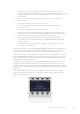
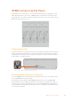
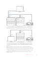
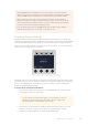
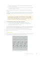
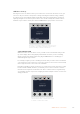
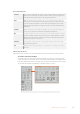
Table Of Contents
- Getting Started
- Switching your Production
- Additional Features on ISO Models
- ATEM SDI Extreme ISO
- ATEM Software Control
- Switching Modes
- Using ATEM Software Control
- Media Manager
- Audio Mixer
- Camera Control
- Using the Software Control Panel
- Transition Control and Upstream Keyer
- Downstream Keyers
- Processing Palettes
- Media Player Tab
- Output Tab
- Recording ISO Files
- Timecode Generator
- Using the Audio Mixer
- Shaping your Audio Mix using Advanced Fairlight Controls
- Using the 6 Band Parametric Equalizer
- Fairlight Controls Workflow Guide
- Using the Media Page
- Navigating the Browse Window
- ATEM Media Pool
- Image File Types
- Creating a TGA File with an Alpha Channel
- Camera Control
- Using Macros
- Changing Switcher Settings
- ATEM Setup Settings
- Using Adobe Photoshop with ATEM
- Using Multiple Control Panels
- Connecting to a Network
- Connecting to an Internet Router
- Keying using ATEM SDI
- Streaming Video
- HyperDeck Control
- ATEM 1 M/E Advanced Panel
- Using ATEM 1 M/E Advanced Panel
- ATEM Camera Control Panel
- Mixing Audio
- Help
- Regulatory Notices
- Safety Information
- Warranty

4 Now press the arrow button to move to the subnet mask and gateway settings and
make the necessary changes.
5 Once all the subnet mask and gateway number fields are set, press the ‘save changes’
soft button to confirm your settings.
With your camera control panel’s IP address set, the network can now communicate with
your panel.
The next step is to assign the switcher’s IP address on the camera control panel. By telling your
camera control panel your switcher’s IP address, the panel can then identify your switcher on
the network.
TIP If your switcher is located near the camera control panel, it’s helpful to open the
network settings menu on the switcher so you can observe your switcher’s IP address
while entering the IP address number fields on the camera control panel. This is also a
good way to cross check your network settings between each unit.
To set the switcher’s IP address on your camera control panel:
1 Press the arrow soft button to navigate to the ‘switcher IP address’ setting.
2 Using the knobs underneath the LCD, set the numbers for each address field.
3 Press ‘save changes’ to confirm your settings.
Now that your panel has identified the switcher, all the controls on your panel should illuminate.
This lets you know the panel is communicating with your switcher and is now able to control
your cameras via the program return SDI outputs from the switcher to each camera.
If the lights are not illuminated on your panel, check your network settings and ensure the
Ethernet cables are connected correctly.
Panel Layout
Each CCU on your camera control panel is exactly the same with the same controls. The menu
settings are primarily controlled using the left CCU’s LCD and soft buttons.
Each CCU has exactly the same controls.
165ATEM Camera Control Panel