July 2022 Installation and Operation Manual ATEM SDI ATEM SDI
Welcome Thank you for purchasing ATEM SDI for your live production streaming! If you’re new to live production switchers, then you’re about to become involved in the most exciting part of the broadcast industry and that’s live production! There is nothing like live production and it’s so easy to become addicted to the adrenaline rush of editing in real time while the live event unfolds before your eyes.
Contents Getting Started 5 Audio Mixer 35 Plugging in Power 5 Camera Control 36 Plugging in Video Sources 5 Using the Software Control Panel 36 Plugging in a Monitor and Testing Inputs 6 Transition Control and Upstream Keyer 37 Connect a Microphone 7 Downstream Keyers 39 Connecting to a Computer 7 Processing Palettes 39 Setting the Webcam Source 8 Media Player Tab 41 Switching your Production 9 Output Tab 41 Switching Sources using a Cut 9 Recording ISO Fil
General Settings 84 Streaming Video 123 Audio Settings 85 Creating Video Links with ATEM Streaming Bridge 123 Multiview Settings 86 Labels Settings 87 HyperDeck Settings 88 Setting the Output Source 88 Saving and Restoring Switcher Settings 89 Preference Settings 91 ATEM Setup Settings 93 Updating the internal software 94 Setup Page 94 Documentation Page 95 Direct Connection 123 Network Connection 124 Remote Administration 127 Internet Connection 127 Connection Statu
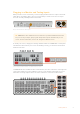
Getting Started At first glance ATEM SDI might seem intimidating with all the connectors and buttons, however your switcher is actually very easy to set up and use. Each feature serves a specific function and it won’t take long to get familiar with your ATEM SDI and know exactly what each feature does.
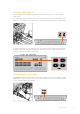
Plugging in a Monitor and Testing Inputs With your video sources connected, you can now plug an SDI monitor into output 1 and check all the inputs are working. This is also a good opportunity to check sources and see if your shots are smoothly switching between each other. Plug an SDI monitor into SDI output 1 TIP ATEM SDI Pro ISO and Extreme ISO models have a powerful multiview feature that lets you see all your inputs, plus program and preview outputs simultaneously on one screen.
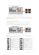
Connect a Microphone Plug a microphone, for example a small wireless collar microphone, into one of the 3.5mm audio inputs. If you are broadcasting an interview, plug the second microphone into the second 3.5mm audio input. You can even plug a music player into one of the audio inputs and mix it into your production. Connect microphones to your ATEM SDI’s mic inputs To add the microphone to your audio mix, press the ‘on’ button. This switches the mic input on air until you press ‘off’.
Setting the Webcam Source Software such as Skype or Zoom should automatically set ATEM SDI as the webcam, so when you launch the application you will see video from your ATEM SDI immediately. If the application doesn’t select ATEM SDI automatically, manually set it to use ATEM SDI as the webcam and microphone. Below is an example of how to set the webcam settings on Skype. 1 In Skype’s menu bar, open the ‘video and audio settings’. 2 Click on the ‘Camera’ menu and select your ATEM SDI from the list.
Switching your Production Switch cleanly between sources using cuts or transitions. A cut will immediately change from one source to another and a transition will gradually change sources over a defined duration. Transitions appear as effects, for example a cross dissolve or mix, a dip to color, or a stylized wipe. TIP There are two switching modes available on your ATEM SDI. The default mode is ‘cut bus’ which lets you change sources as soon as you press an input button.
2 Now press a duration you want for the mix. 3 Press the ‘auto’ button to tell your ATEM SDI want to use an automated transition. 4 Press the input 2 button to perform the mix transition. You will now see inputs 1 and 2 buttons illuminated red while the transition happens and your broadcast changes to input 2. When the transition is complete, input 2 will be illuminated red to indicate it is now live on air.
Controlling Audio When setting up your production or during your broadcast, you will likely want to control audio levels if the sound is too quiet or too loud. When an audio level is too loud it will clip. Clipping means the audio has increased beyond the maximum accepted level and when this happens it can distort and sound unpleasant. Pressing the up and down arrow buttons for each input will increase or decrease the audio level for the respective source.
MUTE On ATEM SDI Extreme ISO, headphone controls include a mute button to silence all audio playback including program audio. This is helpful if a presenter wants to mute program audio while speaking. The button will illuminate red when selected.
To enable picture in picture: 1 Make sure your video to be displayed inside the box is plugged into SDI input 1. 2 Plug your main video into one of the other SDI inputs. 3 In the picture in picture section of the control panel, press the ‘on’ button. You will now see the picture in picture box appear on the screen. To select a different position, press any of the position buttons.
Fade to Black The fade to black button is an easy way to start and end live broadcasts. Fade to black performs a mix to black which happens across all video layers at the same time. This means all video inputs, stills and any upstream or downstream keyers that are visible in your broadcast. When performing a fade to black, the master program audio will also fade out to silence. Simply press the FTB button to perform the fade to black. The button will flash while enabled.
Additional Features on ISO Models ATEM SDI Pro ISO and Extreme ISO model switchers have additional features that give you more options for your broadcast and even more ability to control your production directly from the unit without the need for a computer. Dedicated buttons on the control panel let you switch sources to the SDI outputs, start/stop streaming and start/stop recording.
Direct Streaming via Ethernet ATEM SDI Pro ISO and Extreme ISO switchers’ Ethernet connector lets you stream directly while simultaneously providing the added benefits of ATEM Software Control. You can learn more about this powerful control software in the ‘using ATEM Software Control’ section. TIP You can connect your ATEM SDI Pro ISO or Extreme ISO switcher to a Blackmagic ATEM Streaming Bridge and send broadcast quality video point to point over a local network or the internet.
Now you have copied the stream key for your broadcast, you will need to paste it into the stream details in ATEM Software Control. 1 In ATEM Software Control’s processing palettes, click on the ‘output’ tab. Open the ‘live stream’ palette. 2 Set the platform to YouTube by clicking in the menu and selecting YouTube from the menu list. Set the server to ‘primary’. 3 In the ‘key’ setting, paste the stream key you copied from YouTube. 4 Set the streaming quality to low, medium, or high.
You are now on air! To check your broadcast, click on your account avatar and select ‘back to Twitch’. Once in the main Twitch window, click your avatar icon again and select ‘channel’. You will now see your broadcast on your channel and the live indicator will appear at the top of the window. NOTE If you are using additional ATEM control panels with your ATEM SDI, then you might need a dedicated IP address. For more information, refer to the ‘connecting to a network’ section.
For Android devices, swipe the screen to display the quick menu. Press and hold the hotspot icon and then turn on USB tethering. Now you can press the On Air button on your ATEM switcher to go live! USB TIP Once you’ve finished streaming, we recommend turning off tethering connections to save battery life. Stream Buttons Streaming is built into ATEM SDI Pro ISO and Extreme ISO model switchers, so you don’t need to use any complicated software to get started.
Record Buttons ATEM SDI Pro ISO and Extreme ISO switchers let you record your stream via USB-C using an external disk or flash drive. For example, you can connect a Blackmagic MultiDock 10G and record directly to an SSD. When the disk indicator above your switcher’s record button illuminates green, press the record button and you are now recording your broadcast to disk. To stop recording, press the ‘stop’ button. ATEM Software Control records your stream using H.
Preparing Media External disks can be formatted via a Mac or Windows computer. HFS+ is also known as Mac OS X Extended and is the recommended format as it supports ‘journaling’. Data on journaled media is more likely to be recovered in the rare event that your storage media becomes corrupted. HFS+ is natively supported by macOS. exFAT is supported natively by Mac and Windows without needing any additional software, but does not support journaling.
Using the Multiview ATEM SDI Pro ISO and Extreme ISO switchers have a powerful multiview feature that lets you monitor all SDI inputs, together with the program and preview outputs as a group of views on one screen. The multiview also displays the media player, streaming status, disk recording disk status, audio levels, plus Fairlight EQ and dynamics indicators.
Input Views The input views display all the sources connected to the SDI inputs. Having all inputs on the multiview lets you see the image from every camera so you can make quick decisions. However, they don’t always have to be cameras as you could also have a computer’s video output or a HyperDeck disk recorder connected to the switcher’s inputs and you can monitor them in the input views.
Cache Status The cache status displays the capacity of the switcher’s built in memory buffer. The cache is a small amount of internal memory that continuously records and plays the program output. It acts as a safety measure if the broadcast data rate decreases below a level able to sustain video. The variable nature of the internet is mostly due to network activity or wireless signal strength, so if the broadcast data rate decreases, the buffer data will increase accordingly.
Audio View During your broadcast you can monitor the audio levels for each source and the levels of the program output using the audio view. Audio Meters Each input and the program output has its own audio meter and you can monitor them all simultaneously. If the audio level rises above -10dB the meter will illuminate red to warn you that it is close to the maximum strength of 0dB. Once the level reaches 0dB the audio will clip.
Video Out Buttons The video out buttons on the right side of ATEM SDI Pro ISO and Extreme ISO models are used to switch sources to SDI output 1. The default output 1 source is program. You can also configure the outputs on your ATEM switcher using ATEM Software Control. For more information refer to the ‘ATEM Software Control’ section later in this manual.
ATEM SDI Extreme ISO With ATEM SDI Extreme ISO, there are more button options for your broadcast available directly from the control panel. These include features such as a select bus row of buttons, six direct macro selection buttons and more.
Select Bus The select bus row of buttons are used to assign sources for effects processing and keyers. The select bus is used to select key inputs and can also be used to change your key and fill source to an upstream or downstream keyer while on air. For instance, if there are two angles of a weather presenter in front of a green screen, you can use the select bus to cut between the angles while the key is being broadcast.
Running Macros A macro is a series of events recorded in ATEM Software Control that you can save and then run when needed. All ATEM SDI models support recording and running macros using ATEM Software Control. The macro buttons on ATEM Extreme ISO let you recall and run the first six recorded macros from the switcher’s control panel.
Setting up SuperSource To set up SuperSource, first you need to be able to view it on your monitor. Do this by either assigning SuperSource from the tab in ATEM Software control to a multiview window or by switching to the S/SRC option on ATEM SDI Extreme ISO while a monitor is connected. Positioning Sources In ATEM Software Control open the SuperSource palette and choose from one of the four preset layouts.
Copying Settings To perform the copy function using ATEM Software Control, simply click on the Copy tab and the Copy Box The settings dialogue will appear. You can quickly & easily copy the settings of the currently selected box to any of the other boxes, making an exact clone in just one click! The copied boxes will appear directly behind the master box and will also share the same source as the master.
ATEM Software Control ATEM Software Control is a powerful software control panel that gives you a lot more control over your ATEM SDI switcher. Once you start using ATEM Software Control you will quickly see just how much your switcher can actually do. For example, you can manually perform transitions using the fader bar, select internal sources on the program and preview buttons, mix audio using a mixer with channel faders, set up keyers, load graphics in the media pool and much, much more.
Cut Bus In cut bus mode, as soon as you press an input button, it will immediately switch to air. This is a fast and easy way of switching. In cut bus mode, pressing an input button will instantly switch it to air Program Preview In program preview mode, switching a source is a two step process. This is because pressing an input button puts the source in a preview state so you can decide whether you want to switch it, or perhaps select a different input source.
Press the ‘auto’ or ‘cut’ button to switch the source to air. Using ATEM Software Control ATEM Software Control has four main control windows: Switcher, Media, Audio and Camera. You can open these windows by clicking the three main buttons at the bottom of the interface or by pressing the Shift and left/right arrow hot keys. A general settings window can be opened by selecting the gear icon at the lower left of the interface. You can connect your computer to your ATEM SDI via USB or over a network.
Media Manager The media manager allows you to upload graphics to the media pool in your ATEM SDI. Your switcher has memory for graphics that’s called the media pool and holds up to 20 still graphics with alpha channel that can be assigned to a media player for use in your production. So, for example, you could have the maximum 20 still graphics loaded that will be used on your live production and then assign various stills to the media player as you work.
Camera Control Click on the ‘camera’ tab to open the camera control page. This is where you can control your camera settings such as iris, gain, focus, detail and zoom control on compatible lenses. Plus you can color balance cameras and create unique looks using the DaVinci Resolve primary color corrector that is built into Blackmagic cameras. For detailed information on how to use the powerful camera control features, refer to ‘Using Camera Control’ later in this section.
ATEM mix effects Program Bus Source Select Buttons The program bus source select buttons are used to hot switch background sources to the program output. The source currently on air is indicated by a button that is illuminated red. Preview Bus Source Select Buttons In program preview switching mode, the preview bus source select buttons are used to select a background source on the preview output, this source is sent to the program bus when the next transition occurs.
AUTO/RATE The AUTO button will perform the selected transition at the rate specified in the ‘rate’ display. The transition rate for each transition style is set in the transition palette for that style and is displayed in the ‘rate’ window of the transition control block when the corresponding transition style button is selected. The AUTO button illuminates red for the duration of the transition and the ‘rate’ display updates to indicate the number of frames remaining as the transition progresses.
Downstream Keyers TIE The TIE button will enable the downstream keyer, or DSK, on the preview output, along with the next transition effects and tie it to the main transition control so that the DSK can be taken to air with the next transition. The DSK will transition at the rate specified in the ‘rate’ display of the transition control block. If the DSK is tied, the signal routing to the clean feed 1 is unaffected.
Palettes Tab The ‘palettes’ tab contains the following processing controls. Color Generators Your ATEM switcher has two color matte generators which can be configured from the color generators palette using a color picker or by setting hue, saturation, and luminance levels. SuperSource ATEM SDI Extreme ISO includes a feature referred to as SuperSource that will allow you to arrange multiple sources on the monitor at one time. Refer to the ‘Using SuperSource’ section for more information.
Media Player Tab The ‘media player’ tab contains controls for your ATEM SDI’s media player and connected HyperDecks. Media Player Your ATEM SDI switcher has a media player that plays back the stills that are stored in the media pool memory built into the switcher. The menu list is used to select the still that will be played or made available on the media player input to the switcher.
The live stream status will clearly show you are on air by displaying a large red ‘on air’ indicator together with the timecode generator, which you can set using the timecode generator options. Platform Click in the ‘platform’ menu and select the streaming platform for your broadcast. Options include Facebook Live, YouTube Live and Twitch. Server Select the server that is closest to your location by clicking in the settings window and using the menu.
Record Stream If you are recording your stream via USB-C on ATEM SDI Pro ISO or Extreme ISO models, this palette is where you can control your disks and start and stop recording. You can also set a file name and trigger record in all connected Blackmagic cameras. For information on formating media for recording, refer to the ‘preparing media for recording’ section.
Record button Click the record button marked ‘rec’ to start recording. Stop button Click ‘stop’ to stop recording. Display status Enable or disable this feature by clicking the display status checkbox in the record options. The display status will appear in ATEM Software Control at the bottom right side of the user interface and shows the recording status. When recording, the record indicator will illuminate red and displays the current drive and record time remaining.
What’s in the ISO Folder? The record folder will take the name of the record palette. Even though this folder will have multiple ISO files, it also has the main program recording. But when ISO recording, it will be placed inside this folder with the other items. The ISO video files are recorded from each input and placed into a sub folder called Video ISO Files. Each video file is recorded from each input and is an exact recording of the video connected to that specific SDI input.
Benefits of Editing a Live Project There are multiple benefits of editing a live event. Some of the edits you might need to do can be completed very quickly and then you can render out a new master file before uploading. It means you don’t have to accept the live edit you did while streaming, as now you can make changes to it before uploading it.
Layer 1 Layer 1 has all the main editing between your sources. You will see the clips end to end and sometimes the edit points are cuts and sometimes you can see dissolves. This layer was created from your main input switching. All the edits with the video inputs and the still frame source will be placed on layer 1. Layer 2 Layer 2 is for the downstream keyer. In the ATEM switcher, the downstream keyer is located after the transition block.
To select an alternative edit, you need to follow 2 steps. First you need to select the shot you want and set its in and out point. The next step is to edit it into your timeline, over the shot you currently have. So scroll to the position in the timeline that has the start of the shot you want to replace. You are going to edit over the top of this clip. You should see the alternative shots displayed in the multiview.
You can see how easy it is to do common fixes to your live event. Now select quick export on the top right of the cut page window and you can get a new master file with all these changes applied. Editing in DaVinci Resolve To understand how to use DaVinci Resolve, it’s best to watch some tutorial videos online and download the free version to use for training.
Now when you do quick export, you will be exporting an Ultra HD master, all from an HD switcher! Capture Video When using Blackmagic Desktop Video products, you can record your program output from your ATEM SDI using capture video. Connect your SDI output on the switcher to the input on your desktop video device, for example UltraStudio 4K Mini. To capture: 1 Press the capture settings tab. 2 Select the desktop video device, the capture format and save location from the options. Press Select.
Timecode Generator The timecode generator automatically runs time of day timecode from the moment you launch ATEM Software Control. However, you can reset the counter to zero, or manually enter a new timecode value to start from. To manually set a preset timecode value: 1 Click in the ‘run mode’ menu and select ‘free run’. 2 In the smaller timecode counter, type in a defined timecode value. 3 To confirm the change and set the timecode running, click ‘set’.
The audio mixer displays tally lights for any audio sources that are currently on air or when AFV is selected, as well as audio level, audio balance and buttons for selecting which audio should be used Below each audio source is an audio level meter, a fader for setting the maximum audio level, and a knob for setting the left/right audio channel balance.
Audio Balance The audio mixer supports stereo audio from each audio source. If you wish to change the left and right audio channel balance for a camera or other audio source, adjust the knob to the desired balance point. The audio meter for Cam1 is shown in gray to indicate that its audio will not be used as neither of its ON or AFV buttons are enabled. Cam2 has AFV selected but its audio is not currently being used as the camera is not on air as is indicated by its dull yellow tally light.
Headphones Settings On ATEM SDI Extreme ISO the headphones volume knob lets you adjust the audio monitor levels of the headphones without affecting the program output audio. Click the ‘mute’ button underneath the headphones volume knob to mute audio monitoring.
sound slightly ahead of the video. This is because analog audio is independent of the video inputs and is coming directly from an external source, while the SDI inputs might have some delay depending on upstream equipment, such as some cameras and video processors. Setting the audio delay will ensure the analog audio input is perfectly AV synced to the video inputs from cameras.
Each band of the 6 band parametric equalizer has a column of settings. These settings will differ based on which band you are controlling, and what filter type you are using. Each audio input has its own 6 band parametric equalizer TIP You can learn more about band filters later in this section. If you want to make changes to a setting, you will first need to make sure the band is enabled. Click on a band label to enable it. When enabled, the button label is illuminated blue.
Range Presets The frequency range for each band is defined by the range preset buttons. For example, low is labeled ‘L’ and covers the frequency range from 30 to 395 Hz. As a quick example of how the range presets define the frequency range, select a notch filter from the band filter menu and then click on each range preset. You will see the filter effect move to a position along the graph curve that corresponds to the range preset you choose.
A description for each filter type is provided below. Bell High Shelf Low Shelf This filter is used to increase or decrease a range of frequencies surrounding a defined frequency. Lets you increase or decrease the level of volume for higher frequencies along the graph. Lets you increase or decrease the level of volume for lower frequencies along the graph. Notch High Pass Low Pass This filter lets you remove, or cut, a defined frequency.
Common Dynamics Settings The expander/gate, compressor and limiter share common settings that let you shape how each function affects the audio. For example the level at which the function initiates, how long the function is applied, the strength of the function, etc. The settings available differ depending on the dynamics control you are using. Threshold Sets the sound level at which the function activates.
Make Up The make up setting lets you increase the overall signal in combination with compression settings. With loud parts of the audio reduced using compression, you can now use the make up control to boost the overall sound without clipping. Limiter The limiter prevents peaks of the signal from exceeding a set maximum level. A limiter is helpful to prevent hard clipping. For example, if you set the limiter to -8 dB, the input signal will never exceed that level.
Fairlight Controls Workflow Guide This section describes a basic workflow to help you get started using the Fairlight controls to refine and enhance your audio mix. 1 Generally, the first step to optimizing your mix is to normalize all the inputs so they are all at their maximum strength without clipping. This is normally done by increasing or decreasing the input gain level for each input so their signal peaks just below 0dB on the channel strip’s level indicator.
Keep reading this section for information on how to use the media page in ATEM Software Control. Navigating the Browse Window The browse window is a simplified file browser that lets you navigate your computer to look for graphics files. All attached drives on your computer are displayed, and you can select folders from them. View sub folders by clicking on the arrows next to each folder. The ‘preview’ window will show any selected graphics files.
The file name for each loaded file is displayed underneath the slot so you can easily keep track of files you have loaded. This is very useful as you will see a list of media pool still and clip numbers and their file names in the media player palette on the switcher page. Numbers are displayed on slots in the media pool to clearly show which slot is assigned to the media player.
Image File Types The ATEM media page can use many different file formats including TGA, PNG, BMP, GIF, JPEG and TIFF. Formats such as TGA include a separate alpha channel together with the RGB color channels. This lets you embed a matte, or key image, inside that alpha channel. When a TGA image is loaded in the media player, ATEM Software Control will automatically detect the key image in the alpha channel and load it as the linear key source.
You will now see an alpha channel appear underneath the RGB color channels. The alpha channel contains a grayscale version of the combined color channels in your graphic. Don’t forget to click on the alpha channel’s ‘eye’ icon to make sure it is selected so it will be included when the TGA file is saved. 5 Your selection has now been used to create the grayscale matte in the alpha channel. If you want to, you can now go to the ’menu’ bar and click ‘select/deselect’ to remove the selection marquee.
7 Click ‘save’. A targa options box will appear asking which resolution you want to save. Select ’32 bits/pixel’. This provides enough data for four 8 bit channels which includes the red, green and blue color channels, plus the alpha channel. Click ‘OK’. ) Your TGA file is saved. Now you can open ATEM Software Control and load the file into the media pool. From there, drop the graphic into the media player and the alpha channel you saved will automatically be loaded into the media player key source.
Camera Control ATEM SDI lets you control Blackmagic SDI cameras remotely using ATEM Software Control, or directly from the unit when using ATEM SDI Extreme ISO. This means you can adjust camera settings such as iris, gain and zoom with compatible lenses and color balance cameras using a built in DaVinci Resolve color corrector.
ATEM Camera Control. Camera Control Panel Launch ATEM Software Control and click on the ‘camera’ button located at the bottom of the software window. You’ll see a row of labeled Blackmagic camera controllers containing tools to adjust and refine each camera’s image. The controllers are easy to use. Simply click the buttons using your mouse, or click and drag features to adjust.
Detail Use this setting to sharpen the image from your cameras live. Decrease or increase the level of sharpening by selecting: Detail off, detail default for low sharpening, medium detail and high detail. Color Wheel The color wheel is a powerful feature of the DaVinci Resolve color corrector and used to make color adjustments to each YRGB channel’s lift, gamma and gain settings. You can select which setting to adjust by clicking on the three selection buttons above the color wheel.
The iris/pedestal control illuminates red when its respective camera is on air. Zoom Control When using compatible lenses with an electronic zoom feature, you can zoom your lens in and out using the Zoom control. The controller works just like the zoom rocker on a lens, with telephoto on one end and wide angle on the other. Click on the zoom control, located above the coarse slider and drag up to zoom in, or drag down to zoom out.
Click on the auto focus button or drag the manual focus adjustment left or right to focus a compatible lens. Manual Focus Adjustment When you want to adjust the focus on your camera manually, you can use the focus adjustment located at the bottom of each camera controller. Drag the wheel control left or right to manually adjust focus while viewing the video feed from the camera to ensure your image is nice and sharp. Camera Gain The camera gain setting allows you to turn on additional gain in the camera.
DaVinci Resolve Primary Color Corrector If you have a color correction background, then you can change your camera control from a switcher style CCU interface to a user interface that’s more like a primary color corrector on a post production color grading system. Blackmagic cameras feature a DaVinci Resolve primary color corrector built in. If you have used DaVinci Resolve, then creatively, grading in the Blackmagic camera will be identical so you can use your color grading experience for live production.
Color Wheels Click and drag anywhere within the color ring Note that you don’t need to drag the color balance indicator itself. As the color balance indicator moves, the RGB parameters underneath change to reflect the adjustments being made to each channel. Shift-Click and drag within the color ring Jumps the color balance indicator to the absolute position of the pointer, letting you make faster and more extreme adjustments.
Lum Mix Setting The color corrector built into Blackmagic cameras is based on the DaVinci Resolve primary color corrector. DaVinci has been building color correctors since the early 1980’s and most Hollywood films are color graded on DaVinci Resolve than any other method. This means that your color corrector built into the camera has some unique and creatively powerful features. The YRGB processing is one of those features. When color grading, you can choose to use RGB processing, or YRGB processing.
Camera Control using ATEM SDI Extreme ISO ATEM SDI Extreme ISO allows you to control Blackmagic camera settings including iris, gain, focus and shutter directly from the switcher’s control panel. The camera control buttons are located above the audio options for each input. You can adjust the camera settings in much the same way as the camera control panel in ATEM Software Control.
Focus To use your camera’s auto focus feature, hold down the focus button for three seconds. To manually adjust the focus: 1 Press the focus button to select the feature. 2 Press the arrows up or down to manual focus while viewing the video feed from the camera to ensure your image is nice and sharp. Black To adjust the black level: 1 Press the black button to select the setting. 2 Press the up arrow to increase the black level or the down arrow to decrease.
Camera Control using Mini Converter SDI Distribution Blackmagic Mini Converter SDI Distribution features a single SDI input and 8 SDI outputs. When connected to ATEM SDI, Mini Converter SDI Distribution allows you to control multiple Blackmagic SDI cameras from a single switcher SDI output. You can control up to 4 cameras from ATEM SDI and ATEM SDI Pro ISO model switchers and up to 8 cameras from ATEM SDI Extreme ISO.
Using Macros What is a Macro? A macro is an easy way to automate a sequence of switcher actions so you can repeat the sequence at the press, or click, of a button. For example, you can record a sequence of transitions between several video sources, including key effects, audio mixer adjustments, camera control settings and more. Record all your actions to a macro button, then when you press that button all your recorded actions will be instantly performed.
Recording a Macro using ATEM Software Control In the example below, we’re going to create a macro that will set your ATEM switcher to perform a 3 second mix transition from color bars to color 1, pause for 2 seconds, then perform a 3 second mix transition to black. Try building this macro on your ATEM switcher so you can learn the steps in creating macros. 1 Launch ATEM Software Control and open the macros window. 2 Click on the create button at the top of the macros window to select the create page.
6 Click on the bars button in the program panel on the switcher page. This sets bars to your switcher’s program output. 7 Select color 1 on the preview output. 8 Open the transitions palette and set it to mix. If mix is already selected, make sure your macro records the setting by selecting a different transition type, for example the wipe transition, then clicking on mix again. 9 Now change the transition Rate to 3:00. This sets the mix transition duration to 3 seconds.
ATEM Software Control displays a red border to indicate when you are recording a macro. The ‘add pause’ button located at the top of the red border lets you enter durations for pauses between switcher actions. Enter a name for your macro and a description so you can keep track of the switcher actions recorded in the macro. Building Large Macros Macros can even include triggering other macros as part of recording a macro. This lets you easily build larger macros from multiple smaller macros, i.e.
To compile small macros into a large macro: 1 Start recording a new macro, then while the macro is recording, click on the ‘run’ button to enter the run page. 2 Select ‘recall and run’ to automatically run macros at the push or click of a button, or deselect to load a macro and play it manually. 3 Run your sequence of small macros, with pauses between each one to cover the duration of each small macro, until you’ve completed the large macro. 4 Stop recording.
Macros Window Run Page Play: When Recall and Run is deselected and you have loaded a macro by clicking on a macro button, click the play icon to start playing the macro. Recall and Run: Selecting the Recall and Run feature lets you instantly run a macro by clicking a macro button. Deselecting the Recall and Run feature lets you load a macro by clicking on your macro button. Run the macro by clicking the play button.
Changing Switcher Settings Clicking on the switcher settings ‘gear’ icon will open the settings window where you can change general switcher settings, audio, label, HyperDeck and remote settings. These settings are divided into tabs. If you are using an ATEM SDI Pro ISO or Extreme ISO switcher, you will also have a multiview settings tab.
To set the video standard, select the format you want to use from the ‘set video standard to’ menu and then click on the set button. Any time the video standard is changed, the switcher will remove any stills you have loaded into the media pool, so it’s best to set the video standard before loading any media. Supported Video Input Standards 720p50, 720p59.94, 720p60 HD Video Formats 1080p23.98, 1080p24, 1080p25, 1080p29.97, 1080p30, 1080p50, 1080p59.94, 1080p60 1080i50, 1080i59.
General The settings in the general tab have options for AFV and analog audio input levels. Audio Follow Video Settings You can change the nature of the audio follow video feature for when switching sources. For example, select ‘hard cut audio when switching’ to allow the audio from an input to switch immediately to another. If you want to the audio to smoothly transition over a brief period of time, select ‘add a transition to audio when switching’.
Audio meters can be turned on or off for all the switcher sources and program view by enabling the ‘all on’ button in the multiview settings, or you can turn them on or off individually by clicking the audio meter icon in each view. The opacity of the audio meters can be adjusted by dragging the opacity slider left or right. The multiview also includes a tally feature, so if any of the sources in the multiview are used in a layer on the program or preview outputs, they will be highlighted red or green.
input names support up to 20 characters and are displayed in various menu selection boxes on the software control panel and on the ATEM advanced panel displays. To change an input name, click in the text field, enter the text and click ‘save’. The input name will be updated on the software control panel and external hardware panel if one is connected. It’s a very good idea to change both the short and long labels at the same time, so they match.
Output control menu on Mac OS To set an output, simply click on the ‘output’ option in the menu bar, then scroll the list for the source you want to output. When selected, the output will change immediately. You can see the current source with a tick in the menu item. Program/Preview and A/B Direct Transition Control When you first receive your ATEM switcher, it will be set to program/preview switching which is the current standard for mix/effects switchers.
With ATEM Software Control you can save and restore all your switcher settings for your live production, including key settings, transition styles, media pool contents and more After you have saved your settings you can quick save at any time by selecting File>Save, or by pressing Command S for Mac, or Ctrl S for Windows. Doing so will not overwrite your previous save, but will add a new XML file to your destination folder which is clearly identified with a time and date stamp.
Saving your switcher settings on a laptop gives you the portability to restore your settings on any ATEM switcher. Saving to a USB drive means you can even carry your settings in your pocket. Preference Settings The preferences settings are arranged as ‘general’ preferences and ‘mapping’ preferences. The general preferences contain network settings, transition control and language selection options.
You can change the language for ATEM Software Control in the ATEM Software Control preferences. Button Mapping In the mapping preferences, you can assign inputs to specific buttons on the preview and program rows. The camera drop down menu lets you select a Blackmagic camera for each input, or you can select ‘generic’ or ‘none’. Selecting the correct camera for the input will ensure that all the parameters for that camera are set correctly.
Using Keyboard Hot Keys Hot keys can be used allowing convenient control of some switcher functions using a standard QWERTY keyboard as shown in the following table: Hot Keys Function <1> - <0> Previews source on switcher Inputs 1 - 10. 0 = input 10. <1> - <0> Previews source on switcher Inputs 11 - 20. Shift 0 = input 20.
Updating the internal software To update your ATEM SDI, simply connect the unit to your computer via USB or Ethernet. Launch ATEM Setup. If the software version installed on your computer is newer than the version installed on your switcher, a dialogue box will appear notifying you of an update. Simply click on the ‘update’ button and follow the prompts to update the unit. A progress bar will appear with a notification to let you know when the update is complete.
Panel Switching Mode This setting lets you set your ATEM SDI to use program preview or cut bus switching modes. Refer to the ‘Switching Modes’ section for more information. Picture in Picture Keyer This setting lets you choose to keep the picture in picture on screen indefinitely so you can switch content underneath it, or tie it to the next transition so when you perform the transition, picture in picture will transition off screen with it.
Using Adobe Photoshop with ATEM Installing the ATEM software on your computer also installs a Photoshop plug-in that lets you upload Photoshop graphics direct to your ATEM SDI’s media pool. The plug-in connects to your computer via Ethernet the same way as any other computer running ATEM Software Control on your network. For example, another operator can be updating graphics live in Photoshop during your production and uploading them straight to ATEM’s media player using the plug-in.
Preparing Graphics for Upload For best results, you will want to use a Photoshop document resolution that matches the video standard you’re using with your ATEM switcher. For 1080 HD you should use 1920 x 1080 pixels in resolution. For 720p HD formats you should use 1280 x 720 pixels. When working with Photoshop documents for ATEM, you should not put any content on the background layer, but add all content to the layers above.
When connected to a network via Ethernet, multiple computers can run ATEM Software Control simultaneously, which means multiple operators can be dedicated to separate controls on your ATEM switcher. For example, multiple operators can control media management, camera control and audio mixing. TIP For detailed information about how to control your ATEM SDI using ATEM 1 M/E Advanced Panel refer to the ‘using the ATEM 1 M/E Advanced Panel’ section.
Connect your ATEM SDI to a network and then you can operate your switcher using ATEM Software Control on any computer connected to the same network Using DHCP and Fixed IP Addresses ATEM SDI connects to ATEM hardware panels and your network using a fixed IP address which is set to a default address during manufacture. ATEM SDI Pro ISO, ATEM SDI Extreme ISO and ATEM hardware panels can use a fixed IP address or DHCP.
Below is an example of fixed IP address settings when ATEM SDI is connected directly to ATEM 1 M/E Advanced Panel. ATEM SDI IP Settings IP Address - 192.168.10.240 Subnet Mask - 255.255.255.0 Gateway - 192.168.10.1 ATEM 1 M/E Advanced Panel IP Settings IP Address - 192.168.10.60 Subnet Mask - 255.255.255.0 Gateway - 192.168.10.1 Notice that all the numbers are the same except for the last field of each IP address.
Changing ATEM SDI Network Settings Your ATEM SDI’s network settings are changed using Blackmagic ATEM Setup via USB. Please follow the steps below: Change network settings using the ‘configure’ tab in Blackmagic ATEM Setup. To change the network settings via Blackmagic ATEM Setup: 1 Connect your ATEM SDI via USB to the computer running the setup utility software. 2 Launch Blackmagic ATEM Setup and select your switcher.
Changing Network Settings on ATEM 1 M/E Advanced Panel Change network settings using the system control buttons and LCD soft controls 1 Press the ‘home’ button in the system control buttons to open the LCD home menu. 2 In the home menu, press the ‘network’ soft button to open the network settings. 3 The next step is to decide if you want the panel to use a fixed IP address or to be automatically assigned an IP address from a DHCP server.
5 If the subnet mask and gateway address need to be set, then press the right arrow button in the system control buttons to progress through each setting menu, and use the knobs or the numeric keypad to edit. If at any time you want to cancel the changes, press ‘undo’. 6 When you are happy with your settings, press the ‘save changes’ soft button to confirm.
HOME SETTINGS KEYS MIX WIPE DVE STINGER FTB MEDIA PLAYERS BORDER COLOR MACRO SUPER SOURCE CAMERA CONTROL AUDIO 1 2 3 4 5 6 7 8 9 ENTER 0 RESET DIP AUX On the ATEM 1 M/E Advanced Panel, press the ‘network’ LCD soft button to open the network settings on the LCD, then use the system control arrow buttons to navigate to the switcher IP address setting. Use the soft controls to set the network IP address for your switcher, and don’t forget to save the changes.
Connecting to an Internet Router On ATEM SDI Pro ISO and Extreme ISO model switchers connecting to an internet router via Ethernet lets you stream your broadcast over Ethernet while using the USB-C connector to record to an external drive. To set up direct streaming via Ethernet, first enter the stream details in ATEM Software Control. This will store the streaming information in the switcher.
Getting a Stream Key When setting up your stream, you will need a stream key. This is assigned to your broadcast by your streaming platform, for example YouTube Live, Facebook Live or Twitch. In the following example you can see how to generate a stream key using Facebook Live, YouTube Live and Twitch. Facebook Live 1 Go to your Facebook page and click on ‘create post’. 2 Select ‘live video’ from your create post options. 3 Click on the ‘connect’ tab. 4 Now click on ‘use a persistent stream key’.
Keying using ATEM SDI Keyers are a powerful production tool that allow the arrangement of visual elements from different sources on the same video image. To do this, multiple layers of video or graphics are stacked on top of the background video. Altering the transparency of various parts of these layers allows the background layer to be visible. This process is called keying.
Linear Key A linear key consists of two video sources, which are the fill signal and the key or cut signal. The fill signal contains a video image which is to be stacked on top of the background, while the key signal contains a grayscale mask that is used to define regions of the fill signal to be made transparent. Since both the fill and key signals are video inputs, both signals can be in motion while on screen.
Performing an Upstream Luma/Linear Key Since luma and linear keys use the same parameters, they are set up on the software control panel and advanced panel using a common menu, called the luma key menu. What defines the key as being either luma or linear is in the selection of fill and key sources. In a luma key, fill and key sources are the same. For a linear key, fill and key sources are different.
Upstream key luma/linear key parameters: Mask Enables a rectangular mask that can then be adjusted using the top, bottom, left and right parameters. Pre-Mult Identifies the key signal as a pre-multiplied key. Clip The clip level adjusts the threshold at which the key cuts its hole. Decreasing the clip level reveals more of the background. If the background video is completely black then the clip value is too low.
Downstream Keyer Settings Setting up a Luma/Linear Key on the Downstream Keyer using ATEM 1 M/E Advanced Panel 1 Press the ‘DSK 1 tie’ button to enable the downstream keyer on the preview output. This automatically selects the downstream key menu on the system control LCD, but you can also press the ‘keyers’ button and press the right arrow to enter the menu directly. 2 Press the ‘DSK 1’ or ‘DSK 2’ soft button to select which downstream keyer you wish to use.
animations, you can then key this green to create fast and clean animations of any length. Keying is easy as the green is computer generated so it’s a very flat color that’s easy to key. Combining a background with a fill and chroma key mask Background A full screen image; in the case of a chroma key it is often a weather map. Fill The image you plan to display on top of your background video. In the case of a chroma key, this is video of the meteorologist in front of the green screen.
The chroma sample setting lets you position a cursor over the screen area you want to sample Choose a representative area of your green screen that covers as much of the luminance range of the screen as possible. The default size of the box cursor is well suited to most green screens that are relatively evenly lit, however if there is a lot of variance in your green screen, you can adjust the size of the box by clicking on the slider to the right of the sample window and dragging it up or down.
Background The ‘background’ slider adjusts the opacity of the keyed area. Use this slider to fill in any small foreground artifacts left over in the area of the image you want to remove. We recommend moving the slider until your keyed area is consistently opaque. Key Edge The ‘key edge’ slider moves the edge of your keyed area in or out, helping to remove background elements from the very edge of your foreground or extending the foreground out a little if your key is too aggressive.
Use the color adjustments controls to match your foreground with the background TIP When your key is on air, chroma sampling and preview are locked. While most controls are adjustable while on air, we recommend avoiding changes unless absolutely required. For example making defined color adjustments if conditions change unexpectedly. Pattern Key A pattern key is used to display a geometric cut out of one image on top of another image.
Key/Cut In the case of a pattern key the key/cut signal is generated by the switcher’s internal pattern generator. Pattern Key Settings To set up a pattern key on the upstream keyer in ATEM SDI Extreme ISO models: 1 Select the K1PTN button in the select bus. 2 Select the fill source from the select bus. You can now adjust your pattern settings including selecting the key pattern using ATEM Software Control.
Pattern key parameters: Invert Pattern This button inverts which the region is filled with the fill source. For example, fill a region outside of a circle by positioning the circle wipe as desired and then enabling the invert pattern checkbox. Size Increases and decreases the size of the selected pattern. Symmetry Some patterns may have their symmetry or aspect ratio adjusted. Circle patterns may be adjusted to become horizontal or vertical ellipses.
DVE Key DVEs, or digital video effects, are used to create picture-in-picture boxes with borders. Your ATEM SDI switcher has 1 channel of 2D DVE that allows scaling, rotation, borders and offers a drop shadow. Combining a background, DVE fill and DVE key/cut Background A full screen image. Fill Another full screen that has been scaled, rotated or has added borders and will be overlaid on top of the background.
Adding DVE Borders DVE border parameters The upstream key LCD menu is used to adjust the border parameters for the DVE and picture in picture. Border Enables or disables the border. Color This item appears grayed out because it is not a setting, but rather an indicator to show you the selected border color. You can use this indicator to quickly verify the color of the DVE border. Hue Changes the border color. The hue value is a location on the color wheel.
DVE shadow light source parameters Enable Shadow Enables or disables the drop shadow. Angle Adjusts the direction of the light source on the DVE or picture in picture. Both the border and drop shadow, if available, are affected by changes to this setting. Altitude Adjusts the distance of the light source from the DVE or picture in picture. Both the border and drop shadow, if available, are affected by changes to this setting.
Performing Upstream Keyer Transitions Performing an upstream keyer transition in ATEM Software Control: The upstream keyer is taken on and off the program output using the ‘next transition’ control buttons in ATEM Software Control. Key 1 Take the upstream keyer on or off the program output by clicking the ‘on air’ button. You will notice this is also reflected by the ‘key’ button on your ATEM SDI’s control panel.
Example 3 In this example, the key is on air, indicated by the software control panel’s illuminated ON AIR next transition button. The BKGD and KEY 1 next transition buttons are also illuminated, therefore the background and the upstream key are tied to the next transition. The next transition will transition the background and change the state of the key turning it off so that it is not visible on the program output. There are multiple ways to transition a key to the program output.
Streaming Video Creating Video Links with ATEM Streaming Bridge The ATEM Streaming Bridge allows you to decode the streaming video from any ATEM SDI Pro ISO or Extreme ISO model switcher and convert it back to SDI or HDMI video. It allows you to send video over your local network, or to anywhere in the world via the internet. You can connect ATEM Streaming Bridge in 3 different ways.
Network Connection You can also connect ATEM Streaming Bridge to your network and place it anywhere in your building. This can be useful when you want to live stream to a conference room, or a video projector. As there might be more than one ATEM Streaming Bridge on your network, the main difference is you will need to select the ATEM Streaming Bridge in your ATEM SDI’s network settings. This will ensure your switcher knows what streaming bridge it needs to send its video data to.
Network Status Indicators There are 4 lights on the ATEM Streaming Bridge that provide information on the state of the network connection. The 2 LEDs on the Ethernet connector will show the state of the connection itself. The right orange LED indicates the network is up and connected ok. The left green LED will show network activity. The INTERNET OK indicator will illuminate when the ATEM Streaming Bridge can see the Internet.
Click the ATEM Streaming Bridge icon in ATEM Setup to open the settings Now you can see information such as the ATEM Streaming Bridge name and the network settings. If you are connecting via the local network, then most of the time you can select DHCP. This will let your ATEM Streaming Bridge find its network address on the network automatically and this is how most people connect their computers to a local network.
Setting a streaming key Because anyone can stream to any ATEM Streaming Bridge in the menu, it might be a good idea to set a streaming key to stop anyone crashing into your video link! It’s so easy to select any ATEM Streaming Bridge on your network, that it could become chaos of everyone streaming over the top of everyone else. This is not an issue as you can set a streaming key. This is a password that stops anyone from accessing your ATEM Streaming Bridge.
The problem is your ATEM Streaming Bridge is on your local Ethernet network, however you need it to be visible on the internet. ATEM Streaming Bridge uses port forwarding in your internet firewall to allow the ATEM switcher on the internet to connect via your internet connection to the ATEM Streaming Bridge. If this is not set up, then the ATEM switcher won’t be able to find the ATEM Streaming Bridge.
Connection Status While setting up the network connection, the connection status feature can help you sort out any problems. Some of the information it can show and the cause of the problem are listed below. Visible Worldwide This is a good sign, and it means everything looks to be working correctly. It means port forwarding is set up and working and ATEM Streaming Bridge is ready to receive a video stream from the Internet.
3 Select a custom name for the service. 4 Select the quality you want to stream. 5 Select the export settings button to create a settings file. 6 Email this settings file to the person using the remote ATEM SDI Pro ISO or ATEM SDI Extreme ISO. This settings file is what you will send to the remote ATEM switcher and it has all the settings contained in it so the remote switcher knows where to find this ATEM Streaming Bridge.
Remote ATEM SDI Switcher Now you have this settings file and have emailed it to the person using the remote ATEM SDI switcher, there is a few things they need to do. These steps are quite simple, so it should be very easy for the remote ATEM switcher studio to get these settings loaded. All the remote studio needs to do is go to the ATEM Software Control and select load streaming settings in the stream menu at the top of their screen.
Even though a lot of the ATEM Streaming Bridge setup has been designed to be easy and the setups as automatically as possible, such as the port forwarding settings on your internet firewall, the Internet equipment can be horribly complex and it’s often so complex it’s possible the equipment used on your Internet connection might not have been designed by humans.
1 Launch Open Broadcaster and click on the plus symbol in the ‘sources’ box. 3 Name the new source and click ‘OK’. 5 Now go to your YouTube account. Navigate to the ‘video/live’ option and click ‘get started’. 7 YouTube will now generate a stream name/ key that will direct Open Broadcaster to your YouTube account. Click the ‘copy’ button next to the stream key. Copy the stream key that you will now paste into Open Broadcaster. 2 Select ‘Video Capture Device’.
9 10 To connect Open Broadcaster’s broadcast link to YouTube, click ‘start streaming’ in the bottom right corner of the screen. This establishes the link to YouTube from Open Broadcaster and from here everything will now be set using YouTube Live. 11 Go back to YouTube Live and you will see the webcam program output from your switcher in the background. Click ‘done’. 12 With Open Broadcaster now communicating with YouTube Live, you are ready to begin your broadcast.
HyperDeck Control Introducing HyperDeck Control You can connect up to four Blackmagic HyperDeck disk recorders to your switcher and control them using the HyperDecks palette in ATEM Software Control, or from the system control buttons on an ATEM advanced panel.
Plug the SDI output from HyperDeck Studio HD Mini Plus into an SDI input on ATEM SDI Now all you have to do is tell ATEM Software Control or ATEM hardware panel which input and IP address each HyperDeck is using. You can do this easily in the HyperDeck tab in ATEM Software Control switcher settings, or using the system control soft buttons or LCD menu on an ATEM hardware panel.
Auto Roll You can set a HyperDeck disk recorder to automatically roll video when it is switched to the program output. For example, you can cue a HyperDeck to the point you want your source to begin, then roll the source by pressing its input button on the mix effects program row. As HyperDecks must buffer a couple of frames before commencing playback, the actual cut will be delayed a preset number of frames to ensure a clean transition. This is just like setting a preroll on a videotape machine.
In addition to the text color, each HyperDeck’s selection button also has a tally indicator. Green Outline Indicates a HyperDeck that is currently switched to the preview output. Red Outline Indicates a HyperDeck that is currently switched to the program output, meaning it is currently live to air. You may also see one of the following status indicators above the selection buttons for your HyperDecks. Ready HyperDeck is set to remote and a disk is inserted.
Playback To play media on your HyperDeck, simply switch the HyperDeck source to the preview output and select the clip you want to show. Use the transport controls to cue to the preferred point in your clip. When you switch your HyperDeck to program output, the ‘auto roll’ feature will automatically start playback from this point.
Assigning an input to a HyperDeck In the first menu page, you’ll see the ‘HyperDeck’ indicator in the bottom left corner, and an ‘input’ indicator. Use the control knob under the ‘HyperDeck’ indicator to cycle through the available HyperDecks. Once you have selected a HyperDeck, simply rotate the knob under the ‘input’ indicator to select which input that HyperDeck is connected to on your switcher.
To enter the IP address for subsequent HyperDecks, you’ll need to select the HyperDeck using the first page of the HyperDeck settings menu. Auto Roll You can toggle your HyperDeck’s auto roll function from the second screen of the HyperDeck settings menu. While in the HyperDeck settings menu, use the ‘left’ or ‘right’ arrow buttons in the system control panel to navigate to this screen. While in this menu, press the LCD soft button above the ‘auto roll’ indicator to turn the auto roll feature on.
You can now use the rotating knobs below the ‘hyperdeck,’ ‘clip,’ ‘jog’ and ‘shuttle’ indicators to select HyperDecks, select clips, and jog and shuttle these clips. HOME SETTINGS KEYS MIX WIPE DVE STINGER FTB MEDIA PLAYERS BORDER COLOR MACRO SUPER SOURCE CAMERA CONTROL AUDIO 1 2 3 4 5 6 7 8 9 ENTER 0 RESET DIP AUX The text in the center of the HyperDeck control menu will change to reflect the HyperDeck and clip that you have selected.
ATEM 1 M/E Advanced Panel ATEM SDI switchers are designed to be controlled using their own built in control panels, but if you have a larger production that is more complex and have many sources, graphics and intricate keys to handle, or you need to operate your ATEM SDI from a separate location, an ATEM 1 M/E Advanced Panel can help you.
Using ATEM 1 M/E Advanced Panel ATEM 1 M/E Advanced Panel ATEM 1 M/E Advanced Panel shares the same M/E style button layout as the ATEM Software Control panel. When a change is made to one panel, it will be reflected by the other. For example, if you use the T bar control to manually apply a transition between sources, you will see it happen on the software control panel as well. This section shows how to use all the controls on the advanced panel.
source select row for keyers and routing to auxiliary outputs. Protected sources are program, preview, clean feed 1 and clean feed 2. Program Bus The program bus is used to hot switch background sources to the program output. The source currently on air is indicated by a button that is illuminated red. A blinking red button indicates that the shifted source is on air. Pressing the SHIFT button will display the shifted source. Preview Bus The preview bus is used to select a source on the preview output.
CUT The CUT button performs an immediate transition of the Program and Preview outputs, regardless of the selected transition type. AUTO The AUTO button will perform the selected transition at the rate specified in the auto rate setting located in the LCD ‘home’ menu. The transition rate for each transition type is set in the LCD menu, and is displayed when the corresponding transition style button is selected.
Transition Control and Upstream Keyers ON AIR The ON AIR indicator buttons above each keyer are labeled ON and indicate which of the upstream keys are currently on air. These can also be used to immediately cut a key on or off air. MACRO The macro button is used to enable the macro feature which changes the source select row of buttons to macro buttons corresponding to macro slots.
M/E Buttons As some ATEM switchers have multiple M/Es you can select which one you want to control using the M/E buttons. When an M/E is selected, the LCD menu will change to show the settings that correspond to that M/E panel. Press the M/E buttons numbered 1 to 4 to select an M/E panel to control Fade to Black The FTB button will fade the program output to black at the rate specified in the FTB rate LCD menu setting.
For example, to change the border softness on a wipe transition 1 Press the ‘wipe’ button. 2 Press the right arrow button next to the LCD to move to the third page of settings. 3 Rotate the control knob under the ‘softness’ setting to change the softness of the wipe transition border. If you want to change the direction of the wipe transition 1 Press the arrow buttons to navigate back to the first page of wipe transition settings, or simply press the ‘wipe’ button to return to the first page.
Joystick Control Button Mapping ATEM software and hardware control panels support button mapping so you can assign your most important sources, especially cameras, to the most accessible buttons in the program and preview rows. Occasional sources can be assigned to less prominent buttons. Button mapping is set independently for each control panel so button mapping set on a software control panel will not affect the button mapping set on a hardware control panel.
Cut Transitions The cut is the most basic transition that can be performed on the switcher. In a cut transition the program output is immediately changed from one source to another. Program output for a cut transition. A cut transition can be performed directly from the program bus, or using the CUT button in the transition control block.
To perform a cut transition using the CUT button 1 On the preview bus, select the video source that you want on the program output. The program output will remain unchanged. 2 In the transition control block, press the CUT button. The sources selected on the program and preview buses are exchanged to indicate that the video source that was on preview is now on program and vice versa.
6 At the end of the transition, sources selected on the program and preview buses are exchanged to indicate that the video source that was on preview is now on program and vice versa. Each transition type has its own independent transition rate allowing you to perform faster transitions by simply selecting the transition type and pressing the AUTO button. The previously used transition rate is remembered for that transition type until it is changed.
HOME SETTINGS KEYS MIX WIPE DVE STINGER FTB MEDIA PLAYERS BORDER COLOR Press the ‘mix’ button and set the transition rate using the LCD menu MACRO SUPER SOURCE CAMERA CONTROL AUDIO 2 3 4 5 6 7 8 9 ENTER 0 RESET DIP AUX Mix Transition Parameters Rate 1 SHIFT MACRO The mix transition rate in seconds : frames.
Dip transition parameters Rate The dip transition rate in seconds and frames. Dip Source The dip source is any video signal in the switcher that will be used as the intermediate picture for the dip transition, usually a color generator or media player. Wipe Transitions A wipe is a transition from one source to another and is achieved by replacing the current source by another source with a pattern that forms a shape. For example an expanding circle or diamond. Program output for a wipe transition.
Hold the shift button down to select a shifted source, such as color bars or a color generator. TIP The border source used in a wipe transition can be any source in the switcher. For example, a thick border with the media player as its source can be used for sponsorship or branding. Wipe transition parameters Rate The length of the wipe transition in seconds and frames. Symmetry Symmetry can be used to control the aspect ratio of the pattern.
To perform a DVE transition: 1 On the preview bus, select the video source that you want on the program output. 2 Press the DVE transition type button to select the DVE transition. The DVE settings will appear on the LCD menu. NOTE If the DVE is already being used in an upstream key, the DVE transition type will not be available for selection until the key is taken off air and off next transition. Refer to ‘sharing DVE resources’ later in this section for more information.
Sharing DVE Resources ATEM features a DVE channel which can be used to perform DVE transitions or used in an upstream keyer. When you select a DVE transition, if the DVE is used elsewhere in the system, the DVE transition type will not be available and a DVE unavailable message will be displayed. In order to use the DVE transition you must free the DVE from where it is currently used. Verify that the upstream keys currently on program or preview are not DVE keys and do not have flying key enabled.
4 Press the auto button to perform the transition as an auto transition, or use the fader bar for a manual transition. Graphic wipe parameters Rate Rate specifies the length of the transition in seconds and frames. The rate can be adjusted using the rate knob or by entering a number on the number pad and pressing the set rate button. Normal The normal direction moves the graphic from left to right. Reverse Reverse changes the direction so that it moves the graphic from right to left.
OME 3 Manually move the fader bar from one end to the other to execute the transition. The next move on the fader bar will begin a new transition. 4 During the transition the red and green buttons on the program and preview buses both turn red to indicate that you are in the middle of a transition. The LED indicator on the fader bar also displays the position and progress of the transition. TIP You will also see the ATEM software control panel mirror the move on the hardware panel.
5 Shift select ‘color 1’ on the preview bus. If you wish, you can map buttons such as color bars, black and color generators to any of the main 10 buttons of the program and preview bus for easier access. See the ‘button mapping’ section of this manual for instructions. 6 Press the wipe button in transition control to ensure the macro records the wipe transition selection. 7 In the ‘wipe’ LCD menu, set the rate to 2:00 seconds.
ATEM Camera Control Panel Traditionally, camera control units, or CCUs, have been designed for mounting inside a desk with independent units for each camera. ATEM Camera Control Panel is a portable solution that can be placed on a desk or solid surface with 4 CCUs built in so you can control up to four Blackmagic Design cameras at once. Powering the Panel To power your camera control panel, connect power via the IEC power input on the rear panel using a standard IEC power cable.
If you are using the camera control panel with just your switcher and a computer on a shared network, connect the panel to your switcher, then the spare Ethernet port to your computer. After connecting the camera control panel to your ATEM equipment, you should see the lights on the panel illuminate and the LCDs on each CCU will display their respectively assigned cameras.
NOTE ATEM SDI Pro ISO and Extreme ISO model switchers don’t have a fixed IP address because they are designed to use the DHCP. When connecting these switchers directly to ATEM Camera Control Panel, we recommend setting a manual IP address. When connecting to the camera control panel and a network, set the switcher to DHCP. The network server will assign an IP address and you can then set that as the camera control panel’s switcher IP address so it can communicate with your switcher.
4 Now press the arrow button to move to the subnet mask and gateway settings and make the necessary changes. 5 Once all the subnet mask and gateway number fields are set, press the ‘save changes’ soft button to confirm your settings. With your camera control panel’s IP address set, the network can now communicate with your panel. The next step is to assign the switcher’s IP address on the camera control panel.
LCD Menu Settings Pressing the ‘home’ soft button returns you to main home screen. From the home screen, you can access all your camera control panel’s settings including the network settings, auxiliary for camera control, master black enable and disable settings and the brightness settings for adjusting the lights on the various panel controls. You can also identify the software version installed on your camera control panel and the ATEM switcher your panel is connected to.
You can also disable the banks by holding down the bank soft button until the ‘bank off’ setting appears on the LCD. Turning the banks off lets you change the CCUs to other cameras when needed, with a defined set of cameras ready on each bank you can access at any time. To enable banks, simply press the bank button again.
Master Black Setting the master black setting to on or off enables or disables the master black control, also known as the pedestal control. This is helpful if you want to lock the pedestal so it cannot be accidentally adjusted during production. The pedestal is controlled by turning the ring wheel on the joystick control knob clockwise or counter clockwise. More information on the joystick control is provided in the following sections.
Color Adjustments Contrast The Contrast setting gives you control over the distance between the darkest and lightest values of an image. The effect is similar to making opposing adjustments using the lift and gain master wheels. The default setting is 50%. Pivot When the contrast value is adjusted, you can use the pivot setting to adjust the midpoint of the contrast balance.
Color Balance Controls The red, green and blue color balance knobs in the panel’s mid section are for adjusting the color balance of the lift, gamma and gain levels. The white controls are for adjusting the RGB values for the gain, or highlights and the black controls are for adjusting RGB values of the lift, or the shadows. The black/flare button lets you adjust the RGB values for the gamma, or mid tones, by holding down the button and adjusting the lift RGB knobs.
The lower section of the CCU is where most of the camera control occurs during live production Other buttons and knobs in this section of the CCU are for adjusting the sensitivity of the joystick control, setting the coarse level, locking and unlocking the CCU and more. Details on all the features are provided in the following section. Controlling Cameras This section describes all the features on each CCU and a general overview on how to approach camera control.
TIP The large camera number next to the CCU’s joystick control will also change when you assign a camera. This large identifying number is easy to see and will illuminate red when its camera is live on the program output. Scene Files The numbered buttons along the top of each CCU let you quickly store and recall up to 5 scene file presets.
Recall All When this feature is enabled, you can recall a stored scene file on all cameras simultaneously when you press the corresponding scene file button on a single CCU. For example, you may have a specific setup for each camera that is optimized for a set in your live production. This will likely be a large number of settings that you will want to recall later when you return to that set. The following is an example of how you can recall complex settings for multiple cameras simultaneously.
Relative Control and Absolute Control The camera control panel has two control modes that determine how the panel maintains synchronization between the physical controls and their settings. The two control modes are relative control and absolute control.
TIP When changing a white balance or shutter speed setting, you can increase their speed of change by holding down the corresponding up or down arrow buttons. Hold down the W/B button and press the shutter up and down arrow buttons to set a white balance in degrees Kelvin Color Bars Pressing the ‘bars’ button will set the camera to display color bars. Press again to turn bars off. Shutter Speed The arrow buttons next to the shutter display let you change the camera’s shutter speed.
Gain and Pedestal Level Control The joystick control lets you make fine adjustments to the gain/iris and pedestal/master black levels. Leaning the joystick forwards or backwards opens or closes the camera’s iris, also known as the gain level. As you lean the joystick forwards and backwards, its indicator strip will illuminate, providing an approximate display of the camera’s exposure. For a precise assessment of the exposure f-stop, observe the iris indicator.
You can now lean the joystick all the way up and down and the gain will never rise higher than the limit you have set. TIP When the coarse control is combined with the sensitivity control, you can define an upper and lower limit to the gain control. For example, imagine you want to limit the gain so it never rises above f4.0 because gain above that level will clip highlights in your image. You also want to limit the gain so its minimum setting will be f8.
Panel Active After you are happy with your camera settings, you may want to lock all the controls so they cannot be accidentally adjusted. Pressing the ‘panel active’ button enables the CCU lock so all controls cannot be changed. Press the button again to disable the CCU lock. This can be a helpful feature when you are recording a locked off shot and don’t want the setting adjusted by accident, for example a wide shot of a stadium filling as the crowd enters.
You can adjust multiple audio levels at the same time by connecting a hardware audio mixer to the computer which is running ATEM Software Control Connecting Your Audio Mixer Control Surface 1 Connect your compatible MIDI control surface to your Mac or PC. Most modern control surfaces use USB. 2 Verify your control surface is recognized by your computer as a MIDI device. For Mac OS computers, go to Applications/Utilities/Audio MIDI Setup and launch the application.
Try sliding the gain faders up and down on your hardware control surface and verify that the audio mixer faders show a corresponding movement in the software on your computer screen The MUTE button In the ATEM audio mixer interface, audio is always on, or present in the mix, when the ON button is selected. When the ON button is deselected, audio is not present or is muted.
Help Getting Help The fastest way to obtain help is to go to the Blackmagic Design online support pages and check the latest support material available for your ATEM SDI. Blackmagic Design online support pages The latest manual, software and support notes can be found at the Blackmagic Design support center at www.blackmagicdesign.com/support. Blackmagic Design Forum The Blackmagic Design forum on our website is a helpful resource you can visit for more information and creative ideas.
Regulatory Notices Disposal of Waste of Electrical and Electronic Equipment Within the European Union. The symbol on the product indicates that this equipment must not be disposed of with other waste materials. In order to dispose of your waste equipment, it must be handed over to a designated collection point for recycling.
Safety Information This equipment is suitable for use in tropical locations with an ambient temperature of up to 40ºC. Use only at altitudes not more than 2000m above sea level. No operator serviceable parts inside. Refer servicing to your local Blackmagic Design service centre.
Warranty 12 Month Limited Warranty Blackmagic Design warrants that this product will be free from defects in materials and workmanship for a period of 12 months from the date of purchase. If a product proves to be defective during this warranty period, Blackmagic Design, at its option, either will repair the defective product without charge for parts and labor, or will provide a replacement in exchange for the defective product.