
Operating Guide


United States
Tel: 901.252.8000
800.816.7809
Fax: 901.252.1354
Technical Services
Tel: 888.862.3289
www.tnb.com
www.tnb.com
United States
Tel: 901.252.8000
800.816.7809
Fax: 901.252.1354
Technical Services
Tel: 888.862.3289
19
Connectors & Grounding — Blackburn
®
Grounding Systems
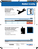
EZGround
™
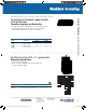
Compression Grounding Connectors
A “snap” to assemble — no special tools required.
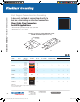
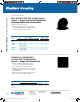
SnapTap
™
Connector
• Designed for bonding and grounding applications using copper,
steel strand and ground rod
• Easily installed with channel locks or pliers
• Made from high-strength aluminum alloy with tin plating
• Offers excellent electrical and mechanical characteristics
• UL
®
467 tested — exceeds performance requirements
With the SnapTap
™
Connector, you can achieve an electrically superior,
pressure-fit connection in seconds without expensive tooling. The connector
is also easy to disassemble, requiring only a flat-head screwdriver to release
the connected body. A one-piece design keeps parts together, minimizing
loss of components prior to assembly. Simply separate the pieces and snap
them in place for installation. An audible “snap” indicates that the connection
is complete and properly installed.
CAT. NO.
CONNECTOR DESCRIPTION PACKAGING
STANDARD
ORDER
QUANTITYMAIN BRANCH
INNER
PACK
OUTER
PACK
JP62 #2 AWG Sol. Copper #6 AWG Sol. Copper 20 200 200
JP66 #6 AWG Sol. Copper #6 AWG Sol. Copper 20 200 200
JP146
1
⁄4" Steel Strand #6 AWG Sol. Copper 20 200 200
JP5166
5
⁄16" Steel Strand #6 AWG Sol. Copper 20 200 200
JP386
3
⁄8" Steel Strand #6 AWG Sol. Copper 20 200 200
JP126
1
⁄2" Steel Strand #6 AWG Sol. Copper 20 200 200
JP126G
1
⁄2" Ground Rod #6 AWG Sol. Copper 20 200 200
JP2614
1
⁄4" Steel Strand (2) #6 AWG Sol. Copper 20 200 200
JP26516
5
⁄16" Steel Strand (2) #6 AWG Sol. Copper 20 200 200
JP2638
3
⁄8" Steel Strand (2) #6 AWG Sol. Copper 20 200 200
JP2612G*
1
⁄2" Ground Rod (2) #6 AWG Sol. Copper 20 200 200
Note: All Toolless Connectors are UL Listed. Only items with (*) are CSA listed.
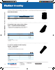
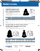
General Usage Instructions
Separate
No special tools required. Use ordinary parallel jaw pliers
to separate the connector into two parts. Hold one side of
connector with pliers and bend opposite side back and forth
until parts separate (see Fig. 1).
Caution: Be careful not to pinch fingers or thumb when separating parts.
Keep fingers out of bend path when bending part against plier jaws.
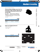
Installation
1. Strip the insulation from each de-energized conductor.
Be careful not to nick the conductor. Clean the conductor
ends with a wire brush or emery cloth if necessary.
2. Place each conductor into the grooves in BODY piece.
Press conductors with pliers to align and seat into grooves
(see Fig. 2).
3. Hold the conductors and BODY piece until it stops. Use
parallel jaw pliers and grip the SNAP and BODY pieces as
shown (see Fig. 3). Apply pressure until connector “snaps”
into place. Visually inspect snap to verify full insertion.
The connection is now complete (see Fig. 4).
Removal
The connector can be disassembled using a flat-head
screwdriver to pry the SNAP piece from BODY piece.
FIG. 1
Bend back and forth
to separate
Separation
point
Body piece
Body
piece
INSTALL
FIG. 2
FIG. 3
Snap
piece
Pivot
groove
Body
piece
FIG. 4
1211_1836_TNB_TNB_Power Connection & Control Cat31_r7.indd 19 2/24/14 3:27 PM