
System information
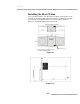


7. Lift the bottom bracket until the screws are tight against the bottom of
the bracket slots. Tighten the screws with the Allen wrench.
8. Push down the top bracket until the screws are tight against the slots,
then tighten the screws.
9. Make sure all four screws are completely tight.
10. Connect the dart head ribbon cable to the 19-pin connector mounted
just inside the slot on the side of the cabinet. Make sure the pins are
properly aligned.
11. Connect the 3-wire connector from the Missed Dart Detector to the other
connector on the side of the cabinet.
12. Slide the matrix shield from behind the web to rest against the side of
the cabinet.
13. Center the shield vertically with the dart head. Attach the shield to the
cabinet using the two cap-head screws previously removed.
14. Repeat the above steps for the left dart head assembly.
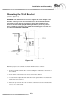
Replacing the Monitor
1. Loosen the monitor stop bracket by turning the 7/16” hex head bolt on
the top of the cabinet; counter-clockwise.
2. Engage the monitor in the cabinet brackets and slide it back into the
cabinet, making sure it is fully engaged with the brackets and slid all the
way back to the stop.
3. Close and lock the cabinet door. Adjust the monitor forward by turning
the hex head bolt (step 1) clockwise. The monitor should be flush with
the opening in the cabinet door.
4. Locate the two power cords coming from the junction box in the bottom
rear of the cabinet. Connect the monitor’s power cord to the shorter of
the two.
5. Connect the monitor’s video cable (15-pin connector) to Video Out on
the CPU.
Basics
2.6