
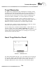
System information
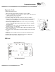


Detector through a 3-wire harness and connector mounted on the side of
the cabinet. The target interface boards are identical and are interchange-
able from side to side.
The target interface board contains two programmed microcontrollers (U1 &
U2) that continuously scan the dart head. When a hit is detected, a signal is
sent to the IOBcard. The signal is translated by the IOB and then sent to
the computer’s microprocessor for processing.
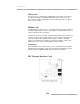
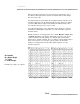
For troubleshooting purposes it is important to know which pins on the tar-
get interface board will give a particular score. This information is given in
the tables below.
With the machine is Test/Setup mode, choose Test - Machine - Target Test
- Segment Test. After removing the switch matrix connector, pairs of pins
can be shorted and opened (quickly - less than 60 milliseconds) with a
jumper wire to simulate a dart hit. The score will not register until the jumper
wire is removed from one of the pins. This procedure can determine
whether a scoring problem is in the switch matrix/segments or in the
machine electronics.
Technical
T2.10
Left Target Interface Table Right Target Interface Table
D = Double
O = Outer Single
T = Triple
I = Inner Single
Example: T6 = Triple six segment.