
System information
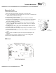


The IOB (Input/Output Board) functions as the “interpreter” for all physical
inputs to the machine. It translates these input signals to a form recogniza-
ble by the microprocessor. Typical inputs include: coin up; button presses
(screen menu selection, access to test/setup mode); and dart head hits. The
IOB’s outputs include a signal to the Dual Triac Board to control the target
illumination lamps and clock signals sent to the Smart Target Interface
Boards. All input/output functions are programmed by Arachnid and stored
on the Programmable System Device (PSD) positioned on the board at
location U3.
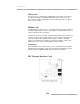
Also located on the board are:
! Two modular jacks (JP1 and JP2) for input/output to the left and
right Smart Target Interface Boards respectively.
! A push button switch (S1), used to set the machine in Test/Setup
Mode or disable the reset watchdog software.
! An indicator light LED (D1), used to display IOB status:
No light = No power to the IOB card.
Red = Power to card - IOB not functioning.
Red/Yellow blinking = Normal Operation.
Red/Yellow blinking slowly = Watchdog disabled.
! Connector JP5, use to connect the machine’s main wiring har-
ness via a 25-wire ribbon cable and a dB-25 connector.
! Connector JP7, used to connect the Watchdog wire to the
Mainboard’s reset connector.
! Connector JP6, used to connect a printer (European models
only).
! Connector JP4, used to communicate with the microprocessor
via a 25-wire ribbon cable to the Mainboard’s parallel port (LPT1)
and then to the portable drive connector on the front of the CPU.
! Two over-voltage protection fuses, located at F1 and F2 (1 amp
@ 250 volt - slow blow).
! Connector JP3, four-pin power connector.
! A Serial ID chip, located at U6.
Technical
T2.4