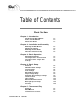
Table of Contents Basic Section Chapter 1 - Introduction Introducing the Black Widow How to use this Manual About other Books 1.2 1.4 1.5 Chapter 2 - Installation and Assembly Mounting the Wall Bracket Hanging the Cabinet Mounting the Dart Heads Final Check and Power Up 2.3 2.4 2.5 2.7 Chapter 3 - Basic Operation Navigating the Menus Selecting a Game - Head to Head Selecting a Game - Single Side Coin Up 3.2 3.3 3.6 3.
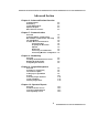
Advanced Section Chapter 6 - Advanced Section Overview Communications Networking League Management Operator Reports Miscellaneous Features 6.2 6.2 6.3 6.3 6.3 Chapter 7 - Communications Overview Central Computer - Requirements Black Widow - Requirements and Setup The Call Window Portable Drive Communications Transferring Files Preparing the Drive Disk Uploads Downloads Connecting a Portable Drive Transferring Machine Configuration 7.2 7.2 7.3 7.4 7.6 7.6 7.7 7.7 7.7 7.8 7.
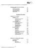
Chapter 11 - Miscellaneous Features Overview Coin Slot Assignment Adjust Lights Settings Steal Credits Option Adjust Credits Screen Top Ten Lists 11.2 11.2 11.3 11.4 11.5 11.
IOB Card Sound Card Video Card Modem Card NIC (Network Interface Card) Hard Drive CMOS Setup Video Monitor Target Illumination Smart Target Interface Board Dart Head Missed Dart Detector Coin & Bill Acceptor T2.3 T2.5 T2.5 T2.6 T2.6 T2.7 T2.7 T2.8 T2.9 T2.9 T2.11 T2.13 T2.14 Chapter T3 - Parts List Door Assembly Cabinet Assembly CPU Assembly Dart Head Assembly Junction Box Assembly T3.2 T3.3 T3.4 T3.5 T3.6 Appendices Setup Menu Flow Chart Test Menu Flow Chart Dart Game Descriptions Glossary A.2 A.4 A.
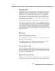
1. Introduction Introduction to the Black Widow 1.2 How to use this Manual 1.4 About other Books 1.
Basics Introduction Congratulations! You have purchased the new generation of dart machines that will take you into the next millennium. Just as Arachnid, Inc. was the originator of electronic darts back in the 70’s, we are proud, once again, to invigorate the coin-op industry with the Black Widow. In the beginning we found that a person’s natural instinct to compete could be applied to electronic darts. With skill level increasing over the years, we saw the need to excite the player again.
Introduction go back to the operator after league play. League standings are transferred to each Black Widow on location. They’re always current and available for players to view on the machine — no need to print, deliver and post. Software revisions are transferred for upgrades, new features and games. Transfers can be accomplished via modem or with a portable disk drive.
Basics Options are easy to understand with selection buttons right beside them. Large 19 inch color screen positioned at eye level for maximum viewing by all patrons. Eye-catching screen graphics encourage play. Animated feat displays showcase player accomplishments.
Introduction About Other Books Although this manual covers all aspects of the machine’s functions, there are times when you will use it in conjunction with other software from Arachnid. Below are listed supplemental references that will help you get the most out of the Black Widow’s options and features. League Management Arachnid League Master System — Overview Part No. 41327 Dartman III — League Management & Scheduling Manual Part No. 38969 A Guide to Using Dartman & DartComm Version 2.X Part No.
Basics Success is a journey not a destination... 1.
2. Installation and Assembly Mounting the Wall Bracket 2.3 Hanging the Cabinet 2.4 Mounting the Dart Heads 2.5 Final Check and Power Up 2.
Basics Installing the Black Widow It is assumed the machine was unpacked according to the instructions located inside the packing lid. With unpacking complete, mounting and assembly of the machine is not difficult. Figures 2.1 and 2.2 show the machine’s dimensions and standard play field measurements. Figure 2.1 Figure 2.2 2.
Installation and Assembly Mounting the Wall Bracket (Refer to figure 2.3) WARNING: The wall bracket is used to support the entire weight of the machine. The lag screws are intended for use in wood-framed walls only. Both screws must be engaged for their entire length into the wood of the wall studs (upright framing members.) If for any reason these conditions cannot be met, STOP the mounting process and contact Arachnid. DO NOT PROCEED. Figure 2.
Basics 5. Mark a vertical line across the horizontal line, centered on the stud. 6. Drill a 3-1/2 inch deep pilot hole, centered on the point where the lines cross, using a 1/4 inch bit. 7. Hold the Z-bracket so the mounting holes are on the bottom and the top of the bracket is projecting away from the wall (see figure 2.3.) 8. Center the Z-bracket across the two studs and note which mounting holes line up over the studs. 9. Secure one side of the bracket using a lag screw and flat washer.
Installation and Assembly so the flange is above the Z-bracket and flush with the wall. 3. Carefully slide the cabinet down the wall to engage the flange behind the Z-bracket. Make sure the flange is fully engaged in the Z-bracket and level before releasing the cabinet. 4. Using a level, make sure the cabinet is vertically plumb. 5. The bottom of the cabinet can be adjusted closer or farther from the wall by rotating the bottom securing bracket as needed (see Figure 2.3.) 6.
Basics 7. Lift the bottom bracket until the screws are tight against the bottom of the bracket slots. Tighten the screws with the Allen wrench. 8. Push down the top bracket until the screws are tight against the slots, then tighten the screws. 9. Make sure all four screws are completely tight. 10. Connect the dart head ribbon cable to the 19-pin connector mounted just inside the slot on the side of the cabinet. Make sure the pins are properly aligned. 11.
Installation and Assembly Final Check and Power Up 1. Make a final check to see that all connections have been replaced and are tight. 2. Close and lock the cabinet door. Remove the key. NOTE: If the door will not close the monitor may not be positioned all the way back against its stop. 3. Remove the two throw line stickers from the accessory bag. Attach them to the floor, one centered on each dart head, at a distance of 98-1/4 inches from the wall.
Basics 6. Turn on the machine using the On/Off (I/O) switch located on the bottom-right of the cabinet. Be patient a few moments while the system boots up. This switch controls the CPU; it must be left on at all times, except when servicing the machine. 2.
Basic Operation Navigating the Menus 3.2 Selecting a Game -- Head-to-Head 3.3 Selecting a Game -- Single Side 3.6 Coin Up 3.8 3.
Basics Navigating the Menus Push Buttons and Button Labels The Black Widow provides for game and option selection through the use of Push Buttons and their associated Button Labels. Button Labels are located on the screen and are associated with individual push buttons mounted on the cabinet door to the right and left of the screen. There are six push buttons on either side of the screen. Pressing the button to the immediate right or left of a Button Label will activate that menu option.
Basic Operation Selecting a Game -- Head-to-Head The following illustrations demonstrate the set up sequence for a typical head-to-head game. Press button to select Head-to-Head menu. Select to play 901 Countdown. Press to change game options. Skip this step to accept the default options. 3.
Basics Pressing here will toggle double or single bull. Other options may appear depending on the the game. When finished choosing options - press here. This box shows credits already in the machine. This box shows number of credits required to play the game. See Coin Up below. After the correct number of credits are entered, press here to begin play. 3.
Basic Operation Game play begins. Press cancel to exit game play any time before the first dart is thrown. 3.
Basics Selecting a Game -- Single Side The folowing illustrations demonstrate the set up sequence for a typical single side game. Choose the type of game from the groups listed on the side you wish to play. The available groups are: Cricket, 01 Games, and Other Games. (The example shows Cricket group chosen for play on the left side.) Select the game to play. 3.
Basic Operation Choose the number of players. Number of credits required shown here. (Arrow) Press “Start” to begin play. Game play begins. Press cancel to exit game play any time before the first dart is thrown. 3.
Basics Coin Up Credits for game play are accumulated by inserting coins into the coin slot or paper currency into the bill acceptor. Coin up is a two step process. First the credits must be inserted and then assigned to the side of the game preferred. Credit Assignment Screen (Described Below) The Credit Assignment Screen (shown above) pops up when the machine is coined-up. Players will press the Left Side or Right Side button to assign the credits to the side on which they wish to play.
4. Basic Setup Overview 4.2 Individual Game Settings 4.3 Sound Settings 4.6 Feats Settings 4.7 Dart Unthrow Setting 4.7 Player Change Delay 4.9 Automatic Player Change Settings 4.9 Volume Control 4.11 Time Settings 4.12 Machine ID and Password 4.15 Blue Light Special Setup 4.18 Free Play 4.
Basics Basic Setup Overview Covered here are the basic operator settings used to configure the machine for casual play. Although the machine ships with default settings that allow play to begin immediately after power up, the operator may want to change some of these settings for regional or local preferences. Accessing the Setup Menus To access the setup and test menus, press the test button.
Basic Setup Basic Setup Tasks The following settings are considered as part of the basic setup of the machine: Games Setup ! Individual Game settings ! Happy Hour ! Credits Needed ! Round Limits ! Last Chance ! Bull ! Cheater Dart Settings ! Feats Settings ! Dart Unthrow Setting ! Player Change Delay ! Automatic Player Change Settings Machine Setup ! Volume Control ! Time Settings ! Blue Light Special Setup ! Happy Hour Setup ! Hours of Operation ! Free Play ! Time and Date Settings ! Machine ID and Passwo
Basics Select Games Setup. Select Individual Game Settings. Selected game shown here. Press to change settings of selected game. Press to change selected game. 4.
Basic Setup Game Settings Screen (Described Below) Individual Game Settings: (Options available on screen will depend on game type) Happy Hour: Credits required to play this game during Happy Hour. Range: 0 to 12 credits. (See Happy Hour Setup on page 4.12) Credits Needed: Credits required for normal and league play. Range: 0 to 12 credits. Round Limits: Limits the amount of rounds that can be played before game ends without declaring a winner. Range: 1 to 99 rounds.
Basics Spread Limit: Toggles Spread Limit On/Off (See Glossary). Out Option: Used to set the requirements for winning the game. Range: Player = Allows player to choose option. Open = Game can be won by hitting the exact number needed to win the game using any segment. Masters = Game must be won by hitting the exact number needed to win using a double, triple or bull. Easy = Game can be won by hitting any number equal to or greater than the number needed to win the game.
Basic Setup Games Setup - Feats Settings Feats Setting Screen (Described Below) When playing Head-to-Head games, the display of player feats could cause distraction to some players. This option allows the feat graphics and sounds to be turned off. Set this option using the ON/OFF button. When finished select Save & Exit. Games Setup - Dart Unthrow Setting Dart Unthrow Setting Screen (Described Below) 4.
Basics The Dart Unthrow feature allows the players to subtract dart throws from any single-sided game in progress. For example: If a player throws out of turn, their darts may be subtracted and the game returned to the point before the error. Pressing the Unthrow Button will subtract darts one at a time. The maximum that can be “unthrown” is eight darts per game. The fig ure below shows the position of the “unthrow” icon during game play.
Basic Setup Games Setup - Games Setup Menu Page 2 Player Change Delay Player Change Delay Screen. (Described Below) The Player Change Delay is the amount of time players have to remove their darts between turns. The timer starts when the third dart hit is registered or when the player change button is pressed. Pressing the More button will increase the delay and pressing Less will decrease the delay. The current value is displayed in the text on the screen. When finished select Save & Exit.
Basics The Black Widow allows for two player change options: Automatic: The game will automatically switch to the next player after three dart hits are registered. In this mode, players can also manually switch players at any time by pressing the Next Player button. Manual: The game will require the Next Player Button to be pressed at the end of each player’s turn. Set Auto Player Change using the Adj Auto Plr Chg button. When finished select Save & Exit. 4.
Basic Setup Machine Setup - Volume Control Select Machine Setup. Machine Setup Sub-Menu Select Volume Control. 4.
Basics Volume Control Screen (Described Below) Use this screen to adjust the output volume of game sounds through the Black Widow’s internal speakers. Pressing More will increase the volume. Pressing Less will decrease the volume. Either button can be held down to quickly make adjustments in the desired direction. The current volume level is indicated on-screen by the moving bar and accompanied by a tone output to the speakers for auditory feedback.
Basic Setup Machine Setup - Time Settings - Time and Date Settings Time and Date Setup Screen (Described Below) The machine’s Date and Time are set on this screen. Use the Hour, Minute, Day, Month, and Year buttons to set the current time and date. The Hour is set in 24 hour time. In the screen above, the time is set for 1:27 p.m. (afternoon). When finished select Exit. Machine Setup - Time Settings - Hours of Operation Hours of Operation Screen (Described Below) 4.
Basics Setting the Hours of Operation will allow the Black Widow to enter Sleep Mode outside the location’s normal business hours. In Sleep Mode the target lights will turn off and the monitor screen will blank out to conserve electricity. While in the Sleep Mode, inserting a coin or pressing any button will return the machine to Normal Mode: Lights and monitor on.
Basic Setup The Happy Hour function allows the operator to offer reduced game pricing for a set time period each day. To activate this function, the time period must be set on this screen and the reduced credits (Happy Hour) set in the Individual Game Settings (page 4.3). Please note the following rules that apply to Happy Hour: ! Happy Hour rates only apply to games that have a Happy Hour rate different than the normal Credits Needed. ! Setting the Begin and End times as the same time, e.g., 6:00 p.m.
Basics Machine Setup - Machine ID and Password Machine Name Machine Name Screen (Described Below) The Machine Name is used to identify the machine when retrieving league statistics. The stats will show which machine the match was played on. Entering a unique name for each machine will help in troubleshooting, should a difficulty arise when collecting league statistics. To enter a name, use the Right and Left buttons to highlight a letter and press Accept.
Basic Setup Machine Setup - Machine ID and Password Modem Password Modem Password Screen (Described Below) The Modem Password is used for security purposes. Without using the correct password the machine will not initiate any communication sessions ( file transfers, statistic collections, software updates, etc.) via modem or portable drive. To enter a password, use the Right and Left buttons to highlight a letter and press Accept.
Basics Machine Setup - Time Settings Blue Light Special Setup Blue Light Special Setup Screen (Described Below) Blue Light Special Used to promote machine play, the Black Widow can offer a free game during times when there has been no activity on the machine. The operator can adjust three settings that affect the frequency of which a free game is offered: ! When the first free game is offered after a period of inactivity has begun. ! How long the offer remains on the screen.
Basic Setup Machine Setup - Time Settings - Free Play Time Settings Menu (Free Play Option Described Below) Free Play The operator can set the Black Widow in Free Play mode by pressing the Free Play Setup button on the menu above. When the button is pressed the Free Play Setup menu bar will turn yellow to indicate free play (no money required) is ON or blue to indicate the option is OFF. Choose the desired state - ON or OFF, then exit the menu and the current state will be stored and activated.
Basics Whoever said, “its not whether you win or lose...” probably lost. 4.
5. Tournament Play Overview 5.2 MatchMaker TM 5.2 Tournament - Scoresheet 5.
Basics Tournament Play Overview The Black Widow provides two methods for tournament play: ! Tournament - MatchMaker TM This method, available only on the Black Widow, will run an 8 or 16 team/player tournament from start to finish. It is completely automatic, calling matches and posting results on-screen. ! Tournament - Scoresheet This method is used for tournament play where tracking of feats and/or MPR (Marks Per Round) and PPD (Points Per Dart) are required.
Tournaments Select Matchmaker or Head to Head (See text for explanation) For a tournament playing a single sided game choose MatchMaker as shown above. To play a Head to Head game in the tournament, select Head to Head then Tournament from the Head to Head menu. Either choice will bring up the tournament set up screen on the next page. If Head to Head was chosen above, select Tournament from this menu. 5.
Basics MatchMaker Main Set up Screen (Described Below) Main Set Up Screen To set up the tournament: ! Press the Single / Double Elimination button to toggle between an 8 Player Double Elimination or the 16 Player Single Elimination. ! Press Select Game and follow the prompts to choose the game and game options to be played in the tournament. ! Press Games Per Match to toggle between; 1 game, 2 out of 3, or 3 out of 5, games per match.
Tournaments Player Input Screen (Described Below) Player Input Screen Players enter their names using the dart head as a keypad, touching the corresponding segment of the letter they wish to input. The limit is 20 characters, consisting of letters, numbers, punctuation marks and spaces. Both dart heads can be used simultaneously to enter player names. The up and down arrow buttons control movement of the Right (red box) and Left (blue box) place markers.
Basics Notes cont.: 3. If there are not enough players to fill the chart, leave blank spaces. The program will generate byes for empty name fields. Do not type bye in a name field - leave them blank! 4. There are two long name boxes and two short nickname boxes at the top of the screen. They show the full name (top box) and nickname or short name (lower box). Some displays of the chart cannot display the full name and will show only the nickname.
Tournaments At this point, the players insert the required credits for this game and press Start to begin their match. If a player fails to show up for a match, the Forfeit option can be selected to end the match. Once selected the player will be prompted to choose the forfeiting player’s name. The match will end and the players will advance in the chart accordingly. When both matches are finished, the machine displays the current status of the chart. Pressing Next will call the next matches. 5.
Basics At the end of the final match the tournament champion is declared with animation and music. Press Continue to display tournament results. The machine displays the top four places in the tournament. Press Continue to exit. General Tournament Notes: 1. In a double elimination tournament, the championship match is played by the last player in the winner bracket against the last player in the loser bracket.
Tournaments different player going first, press the Nxt Plyr button at the beginning of the match to select the other player. Tournament - Scoresheet This feature allows a single game to be played and game statistics to be displayed at the end of the game. It is used where tracking of feats and/or MPR (Marks Per Round) or PPD (Points Per Dart) are required during the tournament.
Basics The Games available per type are: Cricket CRICKET 200 CUT THROAT CRICKET LOW BALL CRICKET WILD CARD CRICKET X01 301 OPEN IN/OPEN OUT 301 OPEN IN/MASTER OUT 301 DOUB IN/DOUB OUT 501 OPEN IN/OPEN OUT 501 DOUB IN/DOUB OUT 701 OPEN IN/DOUB OUT Statistics available at the end of the game by type are: Cricket Stats button: MARKS DARTS ROUNDS MPD MPR WHT HRSE HATTRICK 5 MK RND 6 MK RND 7 MK RND 8 MK RND 9 MK RND DART OUT RND OUT (Total) (Total) (Total) (Marks Per Dart) (Marks Per Round) (White Horse - Tot
Tournaments HATTRICK WICKETS 8 DTOUT 9 DTOUT 10 DTOUT 11 DTOUT 12 DTOUT 5 RNDOUT 6 RNDOUT 5 MK RND 6 MK RND 7 MK RND 8 MK RND 9 MK RND (Hat Trick - Total) (Total) (8 Dart Out) (9 Dart Out) (10 Dart Out) (11 Dart Out) (12 Dart Out) (5 Round Out) (6 Round Out) (5 Mark Rounds -Total) (6 Mark Rounds -Total) (7 Mark Rounds -Total) (8 Mark Rounds -Total) (9 Mark Rounds -Total) X01 Stats button: POINTS DARTS ROUNDS PPD PPR DART OUT RND OUT FREEZES 3 IN BED HATTRICK LOW TON HIGH TON TON 80 MAX TON (Total) (Tota
Basics 4 RNDOUT 5 RNDOUT 6 RNDOUT 3 IN BED HATTRICK LOW TON HIGH TON TON 80 MAX TON FREEZES (4 Round Out) (5 Round Out) (6 Round Out) (3 in a bed - Total) (Hat Trick - Total) (Total) (Total) (Total) (Highest Point Value) (Loss to Freeze Rule) 5.
6. Advanced Section Overview Overview 6.2 Communications 6.2 Networking 6.2 League Management 6.3 Operator Reports 6.3 Miscellaneous Features 6.
Advanced Advanced Section - Overview The following topics are covered in this section: ! ! ! ! ! Communications Networking League Management Operator Reports Miscellaneous Features Communications (Chapter 7) The enhanced two-way communications allows the following tasks to be automated: ! Automated League Management including: ! Match Setup without the use of Team Cards. ! Automatic Collection and Posting of Team Fees. ! Collection of Match Statistics.
Overview handicapping; playing orders; schedules; team and player standings; financial information including team fees and calculation of end of season payouts. Setting up the Black Widow for use in a league system will include topics covered in the Communications, Networking and League Management chapters. Operator Reports (Chapter 10) To assist the operator, the Black Widow stores and provides two kinds of machine statistics. Credit reports help to maintain a record of income.
Advanced Procrastinate Now! 6.
7. Communications Communications Overview 7.2 Central Computer - Requirements 7.2 Black Widow - Requirements and Setup 7.3 The Call Window 7.4 Portable Drive Communications 7.6 Transferring Files 7.6 Preparing the Drive Disk 7.7 Uploads 7.7 Downloads 7.7 Connecting a Portable Drive 7.8 Transferring Machine Configuration 7.
Advanced Communications - Overview In order to use the advanced features of the Black Widow, the operator must communicate with the machine from time to time. Communicate means the transfer of information, files, etc., from a central computer to or from the machine on location.
Communications The Black Widow - Modem To prepare a Black Widow for modem communications, the following tasks must be accomplished: ! ! ! ! ! ! ! Configure and install a modem. Reconfigure the Arachnet. Set the time and date. Input the Machine Name. Input the Modem Password. Set up the call window. Gather information for the central computer’s software.
Advanced Time and Date The machine’s Time and Date are used extensively for communication purposes. For example: League statistics are stamped with the time and date that the match was played and the Call Window (below) uses the time function to set the modem for the number of rings after which it answers incoming calls. To set the Time and Date see page 4.13. Machine Name The machine’s name is used to help the operator distinguish where collected information came from.
Communications Adjust Call Window Screen (Described Below) To set the Call Window, you will set the Begin ( time that the Call Window begins ) and End ( time that the Call Window ends ), the number of rings outside the Call Window and the number of rings within the Call Window. Note: The Call Window is usually set for early morning hours, when the location is closed for business. This is done to lower the possibility that someone at the location will answer the phone and disrupt communications.
Advanced Gathering Information When the machine is completely set up for modem communications; record the following information. (This information is required by the software on the central computer in order to communicate with the machine on location.) ! The name and address of the location. ! The phone number of the line connected to the machine’s modem. ! The Machine Name assigned. ! The Modem Password assigned. ! The Call Window Settings. ! The Machine ID Number ( On-screen ID - see page 4.
Communications ! Team Standings ! Operator Screens ! Software Updates Typical files that are downloaded (from the Black Widow) are: ! League Match Statistics ! Machine Configuration (Configuration files are only transferred from machine to machine. They are downloaded from one Black Widow and uploaded to another Black Widow. See Transferring Machine Configuration below.) Preparing the Portable Drive The first step in uploading or downloading is to preparing a blank drive cartridge (disk).
Advanced Connecting a Portable Drive Connecting a portable drive to the central computer is covered by the manufacturer’s Installation Guide. To connect a portable drive to the Black Widow proceed as follows: 1. Turn off the Black Widow. 2. Unlock and swing open the cabinet door. 3. Connect the drive’s parallel port data cable to the connector on the front of the CPU (see illustration). 4. Connect the portable drive’s power cord to a power source. Turn it on, if necessary, and insert the prepared disk. 5.
Communications can be copied to a prepared portable drive disk and then transferred to other machines. To transfer a machine configuration, proceed as follows: 1. Manually set up the first machine. 2. From the Setup Menu select Machine Setup - Machine Setup Menu Page 2 and press Write Machine Configuration to Jaz Disk. NOTE: Nothing will be written to the portable drive at this time. The machine will create configuration files that will be transferred next time a portable drive is connected to the machine.
Advanced Nobody goes there anymore — it’s too crowded! 7.
8. Networking Networking Overview 8.2 Installing the Network Interface Card 8.2 Building the Network Bus 8.4 Configuring the Arachnet 8.
Advanced Networking Overview This Machine to Machine feature allows multiple machines in one location to be connected together. Networking allows one machine to act as a “master” during modem or portable drive communications, eliminating the need to communicate with each machine individually. Arachnid uses the term “Arachnet” when referring to a network of connected dart machines.
Networking Note: The location of COM IN and COM OUT may be reversed on some network cards. Follow the markings printed on the card. Figure 8.1 Network Interface Card Arachnid Part No. 41233 Once the NIC has been physically configured, it is ready for installation in the machine as follows: 1. Disconnect all relevant cables and power cords connected to the CPU. 2. Remove the CPU from the cabinet. 3. Locate the first card slot on the right side of the CPU case.
Advanced 5. Holding the edge of the network card, carefully align the bottom edge connector with the card slot on the main board. (See illustration at left.) 6. Push the card firmly into the slot. Push down one end of the card, then the other. Use this “rocking” motion until the card is firmly seated in the slot. 7. Secure the card with the retaining screw removed in step 4. 8. Make sure the card has been placed evenly and completely into the card slot. 9.
Networking Cable Type and Length A flat modular phone cable is adequate for short runs between machines of less than 15 feet. For cable runs longer than 15 feet it is best to place a modular phone jack on the wall behind each machine and then run round phone cable between the jacks. Flat cable can then be run the short distance from the wall jack to the machine. When using round cable and wall jacks, care must be exercised in wiring these devices to assure proper wire color orientation.
Advanced Dip Switch 3 “ON” Dip Switches 1, 2 and 3 “ON” Figure 8.4 Dip Switch 3 “ON” All Switches “OFF” Figure 8.5 8.
Networking Dip Switch 3 “ON” Dip Switch 3 “ON” Dip Switches 1 and 2 “ON” Figure 8.6 Setting the Dip-switches The dip-switches on the network card and on the Galaxy main board are used to: enable the network (switches 1 & 2) and terminate the network bus (switch 3). To enable the network, one machine on the network must have dip-switches 1 and 2 turned “ON”.
Advanced Running Reconfigure Arachnet Prior to running Reconfigure Arachnet, perform the following tasks: ! Manually set the Node number of each Galaxy machine connected to the network. ! Reboot all the machines on the network (turn them off and then back on). At the Master Machine, press the Test/Setup button, choose Modem and Arachnet Setup then choose Arachnet Setup. You are given two options on this screen (Figure 8.7): Reconfigure Arachnet and View Arachnet Configuration.
Networking Reconfiguration will begin by detecting any Galaxys on the network. (Described Below) At this point you will see the Galaxy Nodes (1 - 16) turn red, in sequence, as the Master Machine examines each node to see if it exists on the network. The node number of any Galaxys on the network will turn Green, indicating that the node was found and properly configured. When all Galaxys are detected the following screen will display: If there are no other Black Widows on the network Press DONE.
Advanced Black Widow slaves show this screen while the Master Machine is detecting Galaxys. After detecting Galaxys each slave Black Widow will show this screen. (Described Below) Begin configuring the slave Black Widow(s) by pressing any button on the slave when it is displaying this screen (above). When the button is pressed a node (18 - 64) will turn green, indicating that the slave was detected and configured as “On-Line.
9. League Management League Management Overview 9.2 Preparing for League Play 9.2 The Team Fee Option 9.3 Setting up a League Match 9.3 Forfeits 9.11 Collecting League Statistics 9.12 League Standings 9.12 Clearing League Stats 9.
Advanced League Management Overview In conjunction with Arachnid’s Dartman and DartComm software, the Black Widow allows the operator to automate the league management process. The following functions pertain to league management: !"Team Files: Team, Player and Match information is sent to the machine and stored on the hard drive. Teams set up a match through the machine’s menu system by selecting the home and visiting teams.
League Management files and Team Fees (optional) to the Black Widow via modem or portable drive. Turning on the Team Fee Option If you plan on using this option, in addition to transferring the Team Fee information to the Black Widow, the option must be turned on in each machine as follows: Press the Test/Setup button. Choose Setup - League Stats Popularity and Credit Reports - League Stats - Team Fees Setup. The following screen will appear: Press to toggle Team Fee option ON or OFF.
Advanced 0 Press Play League Select a League Choose the Home Team 9.
League Management Team Option Screen (Described Below) Team Option Screen This screen shows four menu options: !"Adj HCP: Allows the players to adjust their handicap. (The Player Edit option must be allowed in the handicap section of the Dartman software prior to generating and sending Team Files) !"Chg Team Allows player swapping (changing the shooting order) and player substitutions. !"Go Back Returns to the previous screen.
Advanced Selecting another player will swap their positions in the line up. Selecting “Choose From Subs List” will bring up the next screen. Use Up and Down to highlight a selection then press Accept. Selecting any “New Substitute” allows manual input of a player name not already on the Subs List as shown below. Player Name Input Screen (Described Below) 9.
League Management The Player Name Input Screen is used to enter a substitute player’s name that is not assigned to the team as a permanent substitute player. To enter a name, use the Right and Left buttons to highlight a letter and press Accept. The letter highlighted will appear in the name box at the top of the screen and the cursor ( _ ) will move right, ready for the next letter. Pressing Accept multiple times will repeat the highlighted letter.
Advanced Completed Team Option Screen Select “Accept” to continue the match setup process. If the Team Fees option is “ON” the machine will prompt the Home Team to insert their money before changing to the next screen. Select the Visiting Team and proceed as above by accepting or changing the team options. When both teams are configured and accepted the machine will set up the first game. After both teams are chosen the machine will set up the first game of the match.
League Management League Description League Name Current Game Type Assigned Credits Player List for this Game (Under Team Name) Credits Required for this Game Game Number in Match Credits Required will be replaced with a Start button once the machine is coined-up. Pressing Start will begin game play. The machine will continue to prompt the players through the game.
Advanced View Team Standings then Press Continue. Insert credits to begin next game or press Stats to view player statistics for the previous game. View stats then press Next Page for second page of stats. 9.
League Management View second page of stats then press Exit Stats to continue. Insert credits to begin next game in match. In addition to individual game statistics, the Black Widow will also display cumulative player stats at the end of each Set. A Set is composed of similar game types, such as 301, that are played consecutively. For example: a match where the first six games are 301, the next six games are Cricket, and the final game is 501, would consist of 3 Sets.
Advanced Collecting League Statistics Once a league match is completed or a forfeit generated this information is stored on the machine for later retrieval. League statistics can be collected via modem or portable drive, then transferred into the Dartman software for storage and manipulation. Match files vs Collection files When statistical information is initially stored on the machine following a match, it is not immediately available for download.
League Management Prev Page buttons. NOTE: Since the standings are displayed in full-screen format this option is available only when both sides of the machine are available for play. The following illustration shows a typical standings screen: Press Next Page or Prev Page to browse team and player standings. Press Cancel when finished. 9.
Advanced Clearing League Stats The Black Widow will continue to record and store league match statistics until they are deliberately cleared from the machine. This means that they are always available for recollection unless they are deleted from the machine’s hard drive. To clear old league stats from the machine: 1. Make sure all stats have been collected and processed by the central computer. 2. At the Black Widow press the Test/Setup Button. 3.
10. Operator Reports Operator Reports Overview 10.2 Credits Collection Screen 10.2 Team Fees Detailed Report 10.3 View Popularity Screen 10.
Advanced Operator Reports Overview The Black Widow has two types of reports available on-screen. The Credits Collection Screen is used for collection and accounting purposes. This report displays both resettable and non-resettable counters. The View Popularity screen is used to keep track of trends in game play and coin drop. This report displays resettable counters. Credits Collection Screen To view this report: Press the Test/Setup button on the CPU.
Operator Reports Under the Temporary and Permanent headings are displayed three types of counters: ! Team Fees: The number of credits taken in for League Team Fees. See Chapter 9 - League Management Overview. As most operators split the Game Credits with the location, Team Fees and Game Credits are displayed separately. ! Game Credits: The number of credits taken in for game play. ! Total Credits: The sum of the Team Fees and Game Credits.
Advanced View Popularity Screen To view this report: Press the Test/Setup button on the CPU. From the Main Setup and Test Menu, select League Stats Popularity and Credit Reports - Popularity Reports - View Popularity. Popularity Screen (Described Below) The popularity screens show the number of games played, the number of players, number of credits, and percentage of total coin drop, for each game.
11. Miscellaneous Features Overview 11.2 Coin Slot Assignment 11.2 Adjust Lights Settings 11.3 Steal Credits Option 11.4 Adjust Credits Screen 11.5 Top Ten Lists 11.
Advanced Miscellaneous Features Overview Features and options covered in this chapter are: ! Coin Slot Assignments: Used to set the credits per coin for individual input devices. ! Adjust Lights Setting: Used to set the lights on or off during the attract mode. ! Steal Credits Option: Used to enable or disable the Steal Credits option. ! Adjust Credits Screen: Used to enable or disable the blinking feature of the Credit Assignment screen.
Miscellaneous Features Coin Slot Assignment Screen (Described Below) Use the More Coins and Less Coins buttons to adjust how many coins ( 1 to 20) have to be inserted to register the number of credits shown. Use the More Credits and Less Credits buttons to adjust how many credits (1 to 20) will register for the number of coins shown. When finished press Exit to save the settings. NOTE: The default for all coin slot assignments is 1 Coin = 1 Credit.
Advanced Use the ON/OFF button to toggle the option. The current setting is displayed in the text on the screen. When finished, press Save & Exit to save the current setting or Cancel to exit without saving any changes. Steal Credits Option This option allows assigned credits to be moved from one side of the game to the other. The operator can enable/disable this option at the machine and adjust how many seconds the Start button must be held down to invoke the Steal Credits Pop Up.
Miscellaneous Features Invoking the Option If the Steal Credits option has been enabled, the players can invoke the option by pressing and holding down the Start button. After the button has been held the required number of seconds the Steal Credits Pop up will display. Steal Credits Pop Up (Described Below) In the example screen above, players are trying to set up a two player cricket game on the right side of the machine. The credits required (6) were assigned to the left side.
Advanced Adjust Credits Screen (Described Below) Use the Adj Blink button to toggle between Blink and Not Blink. When finished, select Save & Exit to save the currently shown setting or Cancel to exit with saving any changes.
Miscellaneous Features Top Ten Edit Screen (Described Below) The example screen above shows the Top Ten List for Countdown (single side). Two players have made the list. All other names are the default of ten minutes; the maximum time allowed to play a speed game. By pressing the corresponding button the operator can clear a player from the list (resets to default) or selecting Clear All will reset the entire list to the default. Select Save and Exit to save the current status of the list.
Advanced Second opinions are popular these days — people think a second then give you their opinion. 11.
T1 Test Menu Test Menu Overview T1.2 System Test Menu Restore Previous Version Verify System Files Check Disk Defragment Disk T1.3 T1.3 T1.3 T1.3 Diagnostics Menu Network Traffic Monitor Network Monitor Modem Monitor System Information IOB Diagnostics Modem Status T1.4 T1.5 T1.5 T1.5 T1.5 T1.5 Machine Test Menu Lamp Test Button Test Video Test Sound Test Display Segment Hit Counters Clear Segment Hit Counters Segment Test Sequence Thru Dart Head Target Diagnostics T1.6 T1.6 T1.7 T1.8 T1.9 T1.9 T1.
Technical Test Menu Overview Arachnid has provided an assemblage of software tools to help the operator or technician maintain and troubleshoot the Black Widow. The tools are divided into three subgroups: ! System Test - Software and Hard Drive tests. ! Diagnostics - IOB, Network and Modem Information. ! Machine Test - Target, Sound, Video, Button and Lamp test. Accessing the Test Menu To access the Test menus, press the test button, then press Test from the Main Setup and Test Menu (See page 4.2).
Test Menu Restore Previous Black Widow Version This option allows the current software version to be removed and reverts to the previous version of Black Widow Software. When selected, the machine prompts for entry of the Operator Password. Upon successful entry of the password, the machine will reboot, the current version will be deleted and the previous restored. Verify System Files Select this option to have the machine check the status of all required system files on the hard drive.
Technical Diagnostics The options in this area are used to view the status and display information about the network, modem and IOB. Diagnostics Menu (Described Below) Network Traffic Monitor The traffic monitor screen displays a visual representation of the activity on the network. Each node (1 to 64) is shown along with its status (Online, Offline, or Local) in the large circle above the node number. The two smaller circles associated with each node show the send (left) and receive (right) status.
Test Menu Network Monitor The network monitor screen displays a log of the last 20 network transactions. The log is cleared an restarted each time the machine is turned off and then back on. Modem Monitor The modem monitor screen displays a log of the last 20 modem transactions. The log is cleared and restarted each time the machine is turned off and then back on. System Information This option will display system information over several screens.
Technical Machine Test Menu The machine portion of the test menu system provides a variety of simple options to test the machine’s hardware. Machine Test Menu (Described Below) Lamp Test Select this option to verify that the hardware and software controls for the target lamps are working. When you press the button, the Lamp Test screen will pop up and the target lamps will turn off. Selecting Exit from the Lamp Test screen will return you to the Machine Test Menu and the target lamps will turn on.
Test Menu The illustration shows the Button Test screen and the buttons on each side of the screen. This test will prompt you to press each button in sequence. If the button is functioning, the prompt will move to the next button. The two bottom buttons are tested by selecting Exit. Video Test This option is used to test the video hardware and software and can be used as a test pattern to make screen adjustments. Video Test Screen (Described Below) Selecting this option, the screen above will pop up.
Technical Sound Test This option verifies that the machine’s audio is functioning properly. Sound Test Screen (Described Below) Pressing Next or Previous will cycle through the game sounds. As each sound’s name is displayed, it will also be played through the machine’s audio circuits. Press Exit when finished. Target Test Selecting this option will open the following sub-menu: Target Test Menu (Described Below) T1.
Test Menu Display Segment Hit Counters This option will display the number of times each segment has been hit since the counters were last cleared. The information is split into three screens. The Next button will sequence through the screens. The last screen contains the Exit button. Clear Segment Hit Counters This option is used to clear (zero) the hit counters described above.
Technical Sequence Thru Dart head This option tests all segments on the dart head in sequential order starting at the top of the dart head. Continue to tap each appropriate segment as prompted on the screen to determine all segments are scoring properly. Target Diagnostics Selecting this option will toggle the mode On or Off. When turned on, the machine will display the raw segment code on the middle right or middle left of the screen for any segment that is struck.
T2. Technical Description General Description T2.2 Power Supply T2.2 Main CPU Mainboard Expansion Cards IOB Card Sound Card Video Card Modem Card NIC (Network Interface Card) Hard Drive CMOS Setup T2.2 T2.2 T2.3 T2.3 T2.5 T2.5 T2.6 T2.6 T2.7 T2.7 Video Monitor T2.8 Target Illumination T2.9 Smart Target Interface Board T2.9 Dart Head T2.11 Missed Dart Detector T2.13 Coin & Bill Acceptor T2.
Technical General Description The Black Widow is a Pentium-class microprocessor controlled dart machine. It consists of three main subsystems: the sealed switch matrix scoring system, the central processing unit (CPU), and a video display. The machine is completely serviceable from the front. All major machine components are accessed by unlocking the front panel and swinging it open.
Technical Description Expansion Cards To install an Expansion Card: 1. Disconnect all relevant cables and power cords to the CPU. 2. Loosen the holding latch located at the top, front, center of the CPU and slide the latch up and out of the way. 3. Slide the CPU out of the cabinet. 4. Locate an empty card slot for the expansion card to be installed. 5. Remove the corresponding slot cover from the chassis by removing the retaining screw and pulling the slot cover up and out of the chassis.
Technical The IOB (Input/Output Board) functions as the “interpreter” for all physical inputs to the machine. It translates these input signals to a form recognizable by the microprocessor. Typical inputs include: coin up; button presses (screen menu selection, access to test/setup mode); and dart head hits. The IOB’s outputs include a signal to the Dual Triac Board to control the target illumination lamps and clock signals sent to the Smart Target Interface Boards.
Technical Description ! Three test points: TP1 = 5vdc; TP2 = Signal Ground; TP3 = Earth Ground Configuration: The IOB Card does not require any configuration prior to installation. Serial ID Chip (U6): The Serial ID chip is used for software protection. Game software will not run unless a unique identification code between the software and ID chip matches. This prevents operation of software that might damage the machine and protects against unauthorized software duplication.
Technical Video Card The video card is a Trident Super VGA Graphic User Interface Accelerator or equivalent, capable of displaying 640 by 480 pixels in 256 colors. All game video is software generated. The video card provides direct output to the color video monitor. Modem Card The Black Widow supports the use of an internal ISA slot modem capable of a minimum data transmission rate of 28,800 bps. The Black Widow does not support external or PCI slot modems.
Technical Description The NIC (Network Interface Card) provides machine to machine communications for multiple machines at one location. Each machine to be networked must have its own interface card. Located on the NIC are: ! Two RJ-11 connectors (JP1-COM IN and JP2 COM OUT), used for network cabling connections. ! A dip-switch bank used to enable the network and set termination resistors. ! A rack of 5 dual-pin jumpers used to set the boards IRQ (Interrupt Request).
Technical ! It is run manually by the user. Warning: Changes to the BIOS settings can severely affect the Black Widow’s performance! Refer to the Main Board Manual shipped with each machine to familiarize yourself with the use of the setup utility before attempting any changes. If in doubt about how to proceed, contact Arachnid Technical Support for assistance. To manually run the setup utility: ! Turn off the machine. ! Connect a keyboard to the CPU.
Technical Description Target Illumination The dart heads are illuminated by two standard fluorescent lamps (F15T8 Cool White) mounted inside the cabinet. The lamps are controlled by a signal from the CPU sent to the Dual Triac Board. The Dual Triac Board is mounted in the power junction box inside the cabinet. The lighting system includes two ballasts (15T8/CW), one mounted adjacent to each lamp. During normal operation the lights remain on.
Technical Detector through a 3-wire harness and connector mounted on the side of the cabinet. The target interface boards are identical and are interchangeable from side to side. The target interface board contains two programmed microcontrollers (U1 & U2) that continuously scan the dart head. When a hit is detected, a signal is sent to the IOB card. The signal is translated by the IOB and then sent to the computer’s microprocessor for processing.
Technical Description Stuck Segments Stuck segments are indicated, in any mode, by a flashing dart head icon on the video display. The stuck segment is shown in a contrasting green color on the icon to allow easy identification. The dart head icon appears on the top-left or top-right of the video display indicating which dart head has the stuck segments Dart Head Each dart head assembly consists of the following components: ! ! ! ! ! ! ! A backboard and mounting brackets.
Technical Dart Head Disassembly/Reassembly To clean or replace parts in the dart head: 1. Remove the 4 retaining screws and remove the catch web. 2. Remove the two screws holding the matrix shield to the side of the cabinet and remove the shield. 3. Disconnect the switch matrix connector from the target interface card. 4. Hold the spider and segments against the backboard while sliding the retaining latches off the spider. Do not remove the resting screws at the bottom of the spider. 5.
Technical Description press it against the back board until it is fully seated. Turn the retaining latches back over the spider to secure the assembly in place. 14. Double check the tail position (toward the connector on the side of the cabinet). Make sure the top 12 o’clock double segment is black and aligned straight up. Remove the assembly and make any adjustments if necessary. 15. If all alignment is correct, reinstall the catch web with the four screws provided. Installation is now complete.
Technical Ideally, the detector should effectively sense darts striking anywhere on the web surface, even the lightest dart. Optimum sensitivity will vary from location to location depending on environmental circumstances. For instance, if a machine is in close proximity to a loudspeaker which gives off vibrations, or possibly a dance floor, sensitivity may need to be decreased to compensate for the interference. Adjust as needed for each location’s needs.
Parts List T3. Door Assembly T3.2 Cabinet Assembly T3.3 CPU Assembly T3.4 Dart Head Assembly T3.5 Junction Box Assembly T3.
Technical Door Assembly Item Part # Description 1 2 3 4 5 6 7 8 40264 40384 40717 40718 40753 40779 41027 40151 40721 6-Button Membrane Switch (2) Bill Acceptor Door Assembly - Wood Frame Door Bezel Main Door Wiring Harness Black Widow Emblem (Not shown) Pivot HInge (2) Coin Mechanism - Complete T3.
Parts List Cabinet Assembly Item Part # Description 1 2 3 4 5 6 7 8 9 10 11 12 13 14 15 16 17 18 21480 27004 32739 33761 34871 37664 40734 40749 40751 40880 40970 40976 41050 41060 41066 41069 38596 40158 41181 40885 Fluorescent Lamp (2) Lamp Socket (4) Fluorescent Ballast (2) Target Interface Cable - 30” Target Interface Cable - 57” Lock Assembly Z-Bracket - Wall Mount 19” VGA Color Monitor Wiring Harness, IOB to Door Harness Lamp Reflector (2) Coin Box Coin Box Lid Assembly 4” Speaker - 2 ohm (2) W
Technical CPU Assembly Item Part # Description 1 2 3 4 5 6 7 8 9 10 14991 40123 40307 40124 40852 41300 40719 40758 40852 41252 40290 40132 41233 11 40716 Video Card CPU Case Card Slot Bracket Power Supply Pentium Motherboard Internal Hard Drive (Programmed) Sound Card IOB to Chassis Out Harness IOB to Motherboard to Portable Drive Harness IOB Card IOB IC Programmed Modem (Optional) Network Interface Card (Optional) T3.
Parts List Dart Head Assembly Item Part # Description 1 2 3 4 5 6 7 8 12575 28258 37376 40741 40742 40743 40723-Left 40724-Right Switch Matrix Matrix Cushion Spider and Segments Target Back Bracket - Upper Left - Bottom Right Bracket - Bottom Left - Upper Right Spacer/Latch Assembly (5) (See diagram below) 40774 Missed Dart Detector Assembly 40757 Catch Web (Not shown) 41046 Matrix Shield (Not shown) Spacer/Latch Assembly 41536 41534 40767 T3.
Technical Junction Box Assembly Item Part # Description 1 2 3 4 5 6 7 8 9 10 11 12 13 14 15 19167 21462 37003 38463 40804 40806 40807 40808 40809 40812 40918 41045 41049 41052 40705 40920 Fuse Holder Rocker Switch Fuse - 4 amp, 250v, Slow Blow, 3AG IEC Power Inlet Socket 14” Switch Box Power Cable 3” Power Jumper Harness (Black) 5” Fuse Jumper Harness (Black) 6” Neutral Jumper Harness (White) 4” Ground Jumper Harness (Green) 31” Female Power Cable Metal Junction Box Jumper Harness, Inlet to Ground La
Appendices A. Setup Menu Flow Chart A.2 Test Menu Flow Chart A.4 Dart Game Descriptions A.5 Glossary A.
Top Ten Lists Countdown Top Ten Speed Cricket Top Ten Double Header Countdown Top Ten Double Header Speed Cricket Top Ten Games Setup Menu Individual Game Settings Cheater Dart Settings Feat Settings Dart Unthrow Setting Games Setup Menu Page 2 Setup Menu Flow Chart Machine Setup Menu Reset to Factory Defaults Volume Control Time Settings... Machine Id and Password... Machine Setup Menu Page 2... Main Setup and Test Menu Setup Menu Software License Agreement Setup... Test... Top Ten List...
Appendices Select Game to Setup Select This Game...
Test Menu Flow Chart System Test Menu Restore Previous Black Widow Version Verify System Files Check Disk Defragment Disk IOB Diagnostics IOB Diagnostics (Read Only) Network Traffic Monitor Network Monitor Modem Monitor System Information IOB Diagnostics... Packets Received: Packets Sent: IOB Version: Last Packet Received: Last Packet Sent: Machine Test Menu Target Test Menu Target Test...
Appendices Dart Game Descriptions Basics ! Each players turn consists of three darts thrown. ! Each dart may be up to eight inches in length and must not exceed 18 grams in weight. ! Players must throw from behind the throw line; positioned 96 inches from the face of the dart head. ! A round has been completed when all players have taken one turn. ! Each player is responsible for playing in the correct shooting order.
are player options with double bull the default. Players must “mark” a number three times before that number is “closed”; a single scoring one mark, a double two marks and a triple three marks. Points are scored when a player closes a number and continues to mark that number. Once both sides have closed a number, no one can score points on that number. To win the game one side must be the first to close all numbers and the bullseye and have equal or greater points than the opponent.
Appendices Quick Draw Quick Draw has the distinction of being the original head-to-head game developed by Arachnid. When you get the green light to begin each round, the on-screen target highlights the active number. You must be quick — you have four seconds and one dart to score before your opponent. Only the first player to hit the active number scores and any dart not reaching the board four seconds after the active number pops up, will be lost. Three active numbers will appear during each round.
X01 Games These single dart head games are the traditional countdown format for one to four players. Players have the choice of starting at 301, 501, or 701. Each player attempts to be the first to reach zero. Scoring more points than required to reach exactly zero results in a “Bust.” During a “bust” round, all points scored during that round are lost. In the event that no player reaches zero in the maximum rounds allowed, the lowest score is the winner.
Appendices Cricket Games Cricket is a game of skill and strategy played with numbers 15 through 20 and the bullseye. A player must “mark” the number three times before that number is “closed.” A single counts one mark, a double two, and a triple three. Points are scored every time a player marks a number he has closed. Once all players have a number closed, no one can score points on that number.
player to close all numbers and bullseye and have equal or more points than the opponents wins the game. A player can win the game at any time with a “Wicket.” End the game with a “Wicket” by scoring a triple 1, triple 2, and triple 3 all in the same turn. You can only “Wicket Out” if you have not previously marked numbers 1, 2, or 3 with any dart during the game. The game has a 20 point spread limit that cannot be deactivated. Team Cricket/400 Played by 4 players as 2 teams.
Appendices Gotcha! Played by 2 to 4 players. The object of the game is to be the first player to go from zero to exactly 301 points. Players try to match the score of their opponent(s) with each dart thrown. Every time there is a match, a bomb is detonated which destroys the opponents score and sets it back to zero (up to three bombs can be detonated per turn).
Speed Cricket The clock times how long it takes to close the regular cricket numbers and the bullseye. Once the start button is pressed, the machine counts down for 10 seconds before the game begins. This is a single player game against the clock so no points are recorded for extra hits on closed numbers. Double bull is the default with an option for the single bull. The Top Ten List can be viewed before playing the game by pressing the menu button.
Appendices Glossary Arachnet Multiple machines networked together in one location. Arachnid The name Arachnid (pronounced ah-rack-nid) was derived from the Latin species name for the spider family. Arachnid the company, was the originator of electronic darts and the League Master System of dart league management. Assist A standard feat. When two players play Cricket on one score, the player taking the game out, gets the Win. The other player gets an Assist.
Highest Out A standard feat. The highest score to go out in a game or series. Last Chance Darts A game option allowing players three darts to take a game out and share the win with the first player to go out. League Match A specified number of games played during one night of scheduled league play. Low Ton A standard feat. During one player’s turn, a score of 100 to 150 points (excluding a Hattrick). Mark One hit scored on an active scoring segment in Cricket. Mark Round A standard feat.
Appendices Round In multiple player games, when all players have taken one turn. In team games, when each team has taken one turn. Round Out A standard feat. The number of rounds taken to win the game. Segment Any of the active pieces in a dart head, which when hit, score points or marks. Single Bull When the inner and outer segments of the bullseye score as one. The inner and outer both score 1 mark or 50 points. Spider The non-scoring lines that separate the dart head segments.
Change is inevitable... ...except from a vending machine. A.
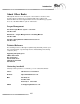
Arachnid, Inc. 6320 Material Avenue P.O. Box 2901 Rockford, Illinois 61132-2901 Black WidowTM Warranty The following Warranty provisions are a part of the Purchase and License Agreement terms and conditions (the “Agreement”) applicable to all sales by Arachnid, Inc. of the Black WidowTM Game Machine.