
Operator`s manual


Page 19
MANUAL ASPIRATOR PUMP
GENERAL: The manual aspirator option is an inexpensive method of adding remote
sampling capabilities to a BW DEFENDER . The Aspirator Pump and Sampling Hose
are joined by a simple quick connect. The D4-AS01 Aspirator Pump is equipped with
the squeeze bulb and an in-line water trap (Order #: D4-WT-1) When ordered, the
D4-AS01 includes a D4-HAS-10 10 ft. (3.1m) sampling hose (longer lengths
available). The Sampling Hose is equipped with a Particulate Filter
(Order #: D4-PF-1).
To operate the Aspirator pump:
1. Attach the Sampling Hose (or Sampling
Probe) quick connect to the in-line water
trap on the Aspirator Pump. Turn right to
lock them together.
2. Attach the outlet hose on the bulb to the
barb connector on the calibration cap.
3. Fit the calibration cap overtop of an
operating BW DEFENDER unit.
4. Squeeze the bulb rapidly to draw sampled
gases into the BW DEFENDER.
Note 1: Keep hoses clean and dry. Clean out clogged tubing by blowing or flushing
with clean water. Allow to dry before use. Both the in-line water filter and
Particulate filters are replaceable.
MOTORIZED SAMPLING PUMP
CONVENIENCE: A BW DEFENDER equipped with motorized Pump and allows you
to monitor in either Active Motorized Sample Mode or Ambient Diffusion Mode simply
at the flick of the switch. The integral pump is never removed during either Active or
Ambient Modes of operation.
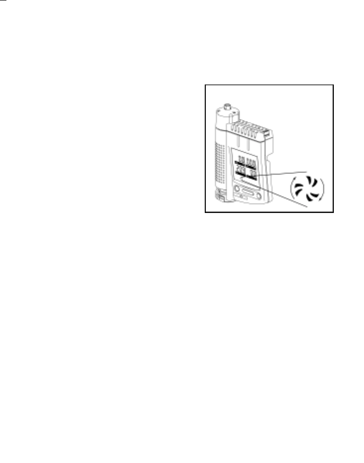
RELIABILITY: The high efficiency
rotary vane pumps act like a small
turbine. BW DEFENDER pumps
provide better reliability and less friction
that result in lower maintenance. The
BW DEFENDER pump is not pressure
sensitive.
POWER: The Sampling Pump is
powered by the BW DEFENDER. Eight
hours of operation is expected.
SAMPLING PUMP INSTALLATION: The BW DEFENDER Sampling Pump, is
installed at the factory if ordered together. The pump can be field installed if ordered
separately.
1. Remove the 4 machine screws on the BW DEFENDER’s sensor endcap and
remove the cap sensor screens. The pump is equipped with sensor screens.
2. Fit the pump unit on the BW DEFENDER in place of the missing endcap.
3. Using 4 machine screws (provided with the pump), attach the pump unit to the
BW DEFENDER. Secure firmly in place.
Note: Overtightening screws results in the Pump Slider Switch being stiff.
19 16