Series 500 Frame Relay/Leased Line Bridge/Router User and System Administration Guide LR1530A-R3, LR1530A-EU-R3, LR1531A-R2, LR1535A-R2 5500099-10 equivalent to 5500086-12 © copyright 2002 by Black Box Corporation.
Federal Communications Commission (FCC) Note: This equipment has been tested and found to comply with the limits for a Class A digital device, pursuant to Part 15 of the FCC Rules. These limits are designed to provide reasonable protection against harmful interference when the equipment is operated in a commercial environment.
INSTRUCCIONES DE SEGURIDAD (Normas Oficiales Mexicanas Electrical Safety Statement) 1. Todas las instrucciones de seguridad y operación deberán ser leídas antes de que el aparato eléctrico sea operado. 2. Las instrucciones de seguridad y operación deberán ser guardadas para referencia futura. 3. Todas las advertencias en el aparato eléctrico y en sus instrucciones de operación deben ser respetadas. 4. Todas las instrucciones de operación y uso deben ser seguidas. 5.
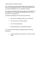
Using This Manual This Installation and Applications Guide provides the basic information required to initially set up and configure the router. This guide is organized into the following sections: “Installation” provides instructions for installing the router. “Typical Applications & How to Configure Them” provides simple configuration examples for typical applications in which the router might be used.
Using the Electronic Reference Manual The router Reference Manuals are provided as Adobe Acrobat PDF files on the accompanying CD-ROM. The PPP Menus Reference File is provided individually for ease of configuration reference. The Adobe Acrobat Reader program is included on the CD-ROM. It is also available for most computer operating platforms from Adobe on the Internet at: www.adobe.com.
Contents 1 - INSTALLATION Unpack the router Select a Site Identify the Connectors Connect to the Console Make the LAN Connections Make the WAN Link Connection Power Up the router Login and Enter the Required Configuration Mandatory Configuration Setting the Link Interface Type (Universal WAN only) Setting the T1/E1Parameters (T1/E1 WAN only) Identify the Status LEDs 2 - TYPICAL APPLICATIONS & HOW TO CONFIGURE THEM Managing the router Using Menus Conventions Basic Frame Relay Configuration Auto Learning the
3 - INTRODUCTION TO FILTERING MAC Address Filtering Pattern Filtering Popular Filters Bridge IP & Related Traffic Novell IPX Frames NetBIOS &NetBEUI (Microsoft Windows) Banyan IP router NetBIOS over TCP Other interesting TCP Ports 57 57 58 61 61 61 61 61 62 62 62 62 APPENDIX A MENU TREES 63 APPENDIX B OCTET LOCATIONS ON ETHERNET FRAMES 67 Octet Locations on a Bridged TCP/IP Frame Octet Locations on a Bridged Novell Netware Frame ETHERNET Type Codes Octet Locations on an IP Routed TCP/IP Frame Octet Lo
Contents V.11 / X.21 DB25 to DB15 Connector Cable V.35 Null-Modem Cable Configuration The link speed must be defined for each of the two units. RS232 / V.
* * * *
1 - INSTALLATION The router is an Ethernet Bridge/Router that provides bridging, IP/IPX routing, and compression over a frame relay permanent virtual circuit or a PPP leased line circuit.. The following instructions provide a quick set-up guide for installation of the router Unpack the unit Rough handling during shipment can damage electronic equipment. As you unpack the router, carefully check for signs of damage. If damage is suspected, contact the shipper.
Installation Identify the Connectors Each unit is configured with both straight (MDI) and crossed over (MDI-X) 10BaseT LAN connectors; the router will auto-sense between the two. Only one connector may be used at a time. The router is produced with four different WAN interface modules: V.35, CSU-DSU, Universal WAN or T1/E1. The type of module in a unit may be determined by looking at the label over the WAN connector on the back panel.
Installation Connect to the Console Connection to the router operator’s console is made through the RJ-45 connector labeled CONSOLE on the back of the router. A RJ-45 cable and RJ-45 to DB9 (female) converter are provided for connection to a DB9 (male) connector. Connect the console port of the router to a computer running an asynchronous communication package or a standard asynchronous terminal. The router supports autobaud rates at 1200, 2400, 9600 or 19,200 bps.
Installation must be configured to the type of connection service that will be used; please see the following section for this procedure. The V.35 module and Universal WAN module in V.35 mode require interface converters that convert from a DB25 connector to a male 34 pin (V.35) connector used for the V.35 service interface. Be sure to secure the cable connector to the router and the communications equipment with connector screws to prevent accidental disconnection.
Installation Power Up the router Once the LAN and Link connections are made and the console is connected to a terminal, you are ready to power-up the router. Connect the DC power cord from the supplied power supply to the back of the router and plug the power supply into the AC wall outlet. Observe the LEDs as the router powers up. The LEDs will go through a flashing pattern as the power-up diagnostics are performed. After the power-up diagnostics are finished, the Power LED will go from red to green.
Installation Mandatory Configuration The router requires a minimum amount of mandatory configuration in order to operate. The following table identifies the configuration parameters that must be defined for proper operation under the operational states shown in the table.
Installation Setting the Link Interface Type (Universal WAN only) The Universal WAN Interface must be configured to match the service to which it will be connected. WARNING: ensure that the connector cable used with the Universal interface module has the correct pinouts for the operational mode selected for the interface (V.11/X.21, V.35, RS232/V.24, or RS530/RS422). Using the incorrect cable connector for the operational mode selected may cause permanent damage to the interface module.
Installation Setting the T1/E1Parameters (T1/E1 WAN only) The parameters requred for a T1 or E1 connection may be obtained from your service provider. These may then be entered via the T1/E1 set-up menu to configure the router for that service. 7 T1/E1 Selection: Location: Main Ä Configuration Ä WAN Set Up Ä Link Set Up Ä T1/E1 Set Up Ä Link mode T1 or E1 Set the service mode to which this router will be connected.
Installation haul LBOs are listed as the length of the cable run (in feet) between the router and the local exchange. E1 service does not require line build out selection. 7 Set Link Interface Type: Location: Main Ä Configuration Ä WAN Set Up Ä Link Set Up Ä T1/E1 Set Up Ä LBO as specifed T1 long-haul LBOs: L0db, L7.5db, L15db, L22.
Installation Some E1 service providers reserve timeslot 16 for network management use.
Installation Identify the Status LEDs The meanings of the four 3-colour Light Emitting Diodes (LEDs) on the front of the router are found in the following chart: Green Green (flashing) Red Yellow Yellow (flashing) Router is running and has passed power-up diagnostics Router is in BOOT mode and is programming the flash Router is powered up but has failed power-up diagnostics Router is decompressing the software into the RAM Router is in BOOT mode Power Green Red Yellow LAN is connected and forwarding Ro
Installation Power Tx Figure 1-4 Front View of the router 16 Rx
2 - TYPICAL APPLICATIONS & HOW TO CONFIGURE THEM The router is an Ethernet Bridge/Router that supports frame relay RAW 1490 permanent virtual circuits, frame relay encapsulated PPP permanent virtual circuits and PPP leased lines. This section will describe how to set up the router using each of its networking functions. The router may be configured as a simple Ethernet bridge, an Ethernet IP router, an Ethernet IPX router, or a combination of the three.
Applications Managing the router Using Menus This section describes the minimum configuration parameters required when setting up the router. Each of the configuration scenarios requires setting of operational parameters on the router. The built-in menu system of the router is used to configure the unit. When navigating around the menu system, a new menu or an option may be chosen by simply typing the number associated with the option that you wish to choose.
Applications Conventions Throughout this section, router menu options are shown that are required for the various configuration choices. The appropriate menu options are shown in each instance in the following format: 7 Configuration Option Name Location: Main Ä Sub-Menu Name Ä Sub-Menu Name Ä Option Name The configuration option is shown as well as the options location within the menu system. The Ä character indicates that a sub-menu level must be chosen. The option name is finally shown in italics.
Applications Basic Frame Relay Configuration North American routers are configured to have frame relay enabled as the default setting. With frame relay enabled, the router will communicate over WAN connections to other frame relay units via frame relay Permanent Virtual Circuits (PVC). From 1 to 40 PVC’s may be defined to connect to other frame relay units. Before the router can establish a PVC connection to another frame relay router, at least one PVC must be defined.
Applications Configuration: The default configuration for routers shipped outside North American is to have frame relay disabled. To run frame relay on these routers, it must first be enabled 7 Frame Relay enable Location: Main Ä Configuration Ä WAN Set up Ä Link Set up Ä Frame Relay enabled The router will request confirmation of the change, enter “yes”. For an router with a CSU-DSU interface, the default clock speed that the router will expect to receive from the DCE link is 64Kbps.
Applications Auto Learning the Frame Relay Configuration The router is pre-configured to query the frame relay service to autolearn the LMI type and the PVC DLCI numbers. This auto-learn function allows the router to be plugged into the frame relay service and auto-learn the PVC configuration to become operational without further manual configuration. Manual configuration is also allowed by modifying the options within each Remote Site Profile and the individual link configuration menus.
Applications Manual Configuration - LMI Type The LMI Type option allows you to manually specify the type of Link Management Interface in use by the Frame Relay service provider for the Frame Relay service. When the LMI type is set to none, the router simply creates frame relay packets and sends them on the defined PVC’s. The links are not checked for errors. There is no congestion control checking. The link is only monitored for control signals.
Applications “Quick Start” Frame Relay Since the router auto-learns the frame relay configuration, only a couple of parameters need to be configured before the unit is fully operational as an IP router for frame relay. Upon initial start up, the router is pre-configured to query the frame relay service to auto-learn the LMI type and the PVC DLCI numbers. The router will then automatically create a remote site profile for each PVC.
Applications By default, PPP is disabled for each of the newly created remote site profiles. If PPP encapsulation is desired, for example to use security, the PPP encapsulation option should be set to “enabled”. By default, when PPP encapsulation is enabled multilink is also enabled.
Applications Basic Leased Line Configuration routers shipped outside North America are configured to have a default setting as a leased line router. The router will operate as a PPP leased line bridge/router if the frame relay function is disabled. The Leased Line router establishes PPP (Point to Point Protocol) WAN connections to other PPP Leased Line router units or to other vendors PPP leased line routers via direct leased line connections.
Applications PPP IP Router Figure 2 - 2 Basic PPP Leased Line Configuration The following steps must be performed on the router unit. 7 Link Speed Location: Main Ä Configuration Ä WAN Set up Ä Link Set up Ä Link Speed The clock speed that the router will expect to receive from the DCE link device must be defined.
Applications Bridge Connection. Once the link speeds have been configured, the router will attempt to establish the link connection to the remote site PPP router. The Bridge connection does not require any configuration for operation. IP Router Connection. Once the link speeds and local IP address have been configured, the router will attempt to establish the link connection to the remote site PPP router.
Applications Should You Bridge or Route? When connecting two Local Area Networks together, the first question to ask is should I bridge or route? The decision to bridge or to route may be decided by how the existing networks have been already set up. Bridging should be used when the network consists of non-routable protocols or routable protocols using the same network numbers. Some protocols can only be bridged; some of the more well known are NetBEUI (used by Microsoft Windows 3.
Applications Configure as an Ethernet Bridge An Ethernet bridge intelligently forwards LAN traffic to remotely connected LANs across the Wide Area Network (WAN). WAN connection LAN #2 LAN #1 Figure 2 - 3 Bridged Local Area Networks Ethernet bridges simply forward information based on Ethernet MAC addresses. If a LAN packet is destined for a device located on a remote LAN, the bridge will forward that packet to the remote LAN.
Applications The router also is pre-configured as an IPX router. This means that if you wish to bridge IPX traffic instead of routing it, you must disable the IPX routing function of the router. Once IPX routing has been disabled, all IPX traffic will be bridged between partner bridges on the WAN. The two Local Area Networks may be bridged together with minimal configuration required.
Applications The size of the subnet mask. defines the subnet mask by using the specified number to reserve a series of contiguous bit locations from the start of the entire IP address. These reserved bit locations are then used as the network portion of the IP address. For example, with a class C IP address, a subnet mask size of 26 will mask the 24 network address bits plus 2 host bits for the subnet address, resulting in 4 subnet addresses being created.
Applications Configure as an Ethernet IP router An Ethernet IP router is used to intelligently route Internet Protocol (IP) LAN traffic to remotely connected LANs across the WAN. Router IP Address 199.169.1.10 WAN connection Router IP Address 199.169.2.12 IP Network Address 199.169.2.0 IP Network Address 199.169.1.0 LAN #1 LAN #2 Figure 2 - 4 IP Routed Local Area Networks IP routers forward IP frames based upon their IP destination address and an internal routing table.
Applications 7 IP Address Location: Main Ä Configuration Ä LAN Set-up Ä LAN IP Set-up Ä IP Address / Subnet mask size The IP address consists of four 8-bit numbers and is represented by 4 fields separated by periods (“.”), where each field is specified by a decimal number (e.g. 199.169.1.10). Each decimal number must be less than or equal to 255 (the maximum value of an 8-bit binary number). The IP address is first specified and then you will be prompted to enter the Subnet mask size.
Applications Define an IP Default Gateway An IP default gateway is an IP router that is resident on the local IP network that this router is connected to and is used to route IP frames for destination networks that do not exist in the routing tables. When an IP frame is received that is destined for a network that is not listed in the routing tables of the router, the router will send the IP frame to the default gateway.
Applications Define an IP Static Route Static IP routes may be defined when one specific router is to be used to reach a destination IP network. The static route will have precedence over all learned RIP routes even if the cost of the RIP learned routes is lower. 7 Edit Static Route Location: Main Ä Configuration Ä IP Routing Set up Ä IP Routes Ä Edit Route Ä Edit Static Route Ä Remote Site Ä Next Hop Ä Cost Ä Add Each static IP route is defined in the Edit Route menu.
Applications Define an IP Subnet Mask An IP network may be divided into smaller portions by a process called sub-netting. A subnet is specified using high end bits of the host field of the IP address for network addressing. This is done with a subnet mask. Thus, the size of the subnet (i.e. The number of bits available for subnet addressing) is the size of the subnet mask minus the length of the network field of the IP address for that class (8, 16 or 24 bits for classes A, B and C respectively).
Applications Configuration: The mask size entered defines the size of the subnet mask from the start of the entire IP address. This allows subnet sizes from 0 to 24 bits. A subnet mask size of 8 in a class A address represents a subnet size of 0 or no subnetting performed. Original IP Network Address 199.169.100.0 Subnet IP Network Address 199.169.100.64 Subnet Mask is 255.255.255.192 Router IP Address 199.169.100.65 Subnet Mask Size 26 Subnet IP Network Address 199.169.100.128 Router IP Address 199.
Applications less than or equal to 255, that is the maximum value of each 8-bit field. The IP address is first specified and then you will be prompted to enter the mask size. The mask size defines the subnet mask by using the specified number to reserve a series of contiguous bit locations from the start of the entire IP address. These reserved bit locations are then used as part of the network portion of the IP address.
Applications Configure as an Ethernet IPX router The router is preconfigured to operate as an IPX router when installed in an IPX network. The router will learn the IPX network numbers from the local LAN and when the WAN connections are established, the router will route the IPX frames to the appropriate destination IPX network. The IPX routing scenario may consist of one of the two following configurations.
Applications examined and looked up in the routing tables. Once the destination IPX address is found in the routing tables, the IPX router sends the IPX frame to the remote partner router that is connected to the appropriate remote IPX network. To configure the router to be an IPX router when both LAN segments contain Novell servers, the IPX network numbers are learned automatically from the routing information and service announcements sent by the servers.
Applications Novell Servers in One Location Only Some Novell LAN installations require that a remote LAN that consists of only Novell IPX clients be connected to a central LAN that contains the Novell servers and some more clients. In this configuration, the router located at the remote site must be configured with the appropriate IPX network numbers. The IPX network number must be configured manually because there is no Novell server at the remote site.
Applications 7 IPX Frame Types Location: Main Ä Configuration Ä IPX Routing Set up Ä Configure LAN Nets Ä Ethernet-II Frames Ä RAW 802.3 Frames Ä IEEE 802.2 Frames Ä 802.2 SNAP Frames Define the appropriate IPX network number for the appropriate frame type. Note that IPX network numbers must be unique. If more than one frame type is to be used, each frame type must have a unique IPX network number.
Applications PPP Link Configuration Overview A PPP (Point to Point Protocol) connection between two routers may use a number of Network Control Protocols (NCP) for communication. An IP router connection will use the Internet Protocol Control Protocol (IPCP) NCP for all IP communications. An IPX router connection will use the Internet Packet Exchange Control Protocol (IPXCP) NCP for all IPX communications.
Applications remote site profile settings. The WAN IPX network number is defined with the IPX Net option in the remote site profile settings. Unnumbered Links An unnumbered link does not use network addressing on the WAN link. The WAN connection is roughly equivalent to an internal connection with each of the two end point routers operating as half of a complete router that is connected between the two endpoint LANs.
Applications Configure Dynamic Host Configuration Protocol The router uses Dynamic Host Configuration Protocol (DHCP) to allow users in a small office environment to simply enable DHCP clients on their workstations and power them up to get their proper initialization. You would then be able to use TCP/IP applications (such as connecting to the Internet). DHCP allows configuration of devices (DHCP clients) to be handled from a central DHCP server.
Applications devices attached to the DHCP Server to be set. The number of addresses to be assigned must also be specified to a maximum of 253. With the DHCP Services and IP Address Pool defined, devices may be attached to the network (up to the maximum specified) and they will be automatically configured.
Applications Configure Network Address Translation (NAT) Support is provided for Network Address Translation (NAT). Network Address Translation is a technique which translates private IP addresses on a private network to valid global IP addresses for access to the Internet. Port translation (NAPT) allows more than one private IP address to be translated to the same global IP address.
Applications The Translation Type option allows you to use Network Address Port Translation. 7 Translation type Location: Main Ä Configuration Ä WAN Set up Ä Remote Site Set up Ä Edit Remote Site Ä Protocol Set up Ä IP Parameters Ä NAT Advanced Ä Translation type Ä Port The configuration options described here are only for initial set up and configuration purposes.
Applications Configure PPP Security The router provides support for both PAP and CHAP PPP security authentication. An outgoing user name, PAP password , and CHAP secret are defined that the router will use when responding to an authentication request from a remote site PPP router. The cold start defaults for the security user name and passwords are as follows. These defaults will exist when the router is first started before and configuration is entered, and after a Full Reset has been performed.
Applications 7 Security Database Entry Location: Main Ä Configuration Ä WAN Set up Ä Edit Remote Site Ä Security Parameters Ä Incoming PAP Password Ä Incoming CHAP Secret Ä Outgoing User Name Ä Outgoing PAP Password Ä Outgoing CHAP Secret The security entries in the security database define the user names and passwords that remote site PPP routers will provide when an authentication request is sent from this router.
Applications Configure Firewall The router provides Firewall security for restricting access between any two networks connected through the router. Firewalls are set up on a per connection basis for the LAN and remote sites. The direction of filtering is from the perspective of the router; incoming traffic is from the network in question to the router, outgoing is from the router to the network. The direction of filtering may be set to incoming, outgoing, both or none.
Applications also wishes to allow all of the TCP traffic from the branch office network to have access to the head office. Anyone in the corporation may have unrestricted access to the Internet. The following steps must be performed on the router to set up the firewall support as desired. First the firewall on the ISP connection (remote site 1) of the WAN is set up.
Applications designated servers list allows you to quickly setup a firewall entry without having to figure out TCP port values. Next, the LAN firewall is set up to restrict access to the LAN. The firewall option is set to “outbound” to have the LAN firewall filter traffic from the router.
Applications 7 Firewall Location: Main Ä Configuration Ä Applications Set up Ä Firewall Set up Ä LAN Firewall Set up Ä Designated Servers Ä FTP Server — 195.100.1.12 Ä WWW (HTTP) Server — 195.100.1.20 The configuration options described here are only for initial set up and configuration purposes. For more information on all of the configuration parameters available, please refer to the router PPP Menus Reference Manual file on the accompanying CD-ROM.
Applications * * * * 56
3 - INTRODUCTION TO FILTERING The router provides programmable filtering which gives you the ability to control under what conditions Ethernet frames are forwarded to remote networks. There are many reasons why this might need to be accomplished, some of which are security, protocol discrimination, bandwidth conservation, and general restrictions. Filtering may be accomplished by using two different methods.
Introduction to Filtering You may easily prevent stations on one segment from accessing all but a specific resource on the other segment; for this, “negative” filtering and the use of “Forward if Destination” would be appropriate. If you want to disallow all but one specific station from accessing any service on the other segment, the use of “Forward if Source” could be used.
Introduction to Filtering The following operators are used in creating Pattern filters. - offset Used in pattern filters to determine the starting position to start the pattern checking. Example: | OR AND NOT 10-20|12-80 This filter pattern will match if the packet information starting at the 10th octet equals the 20 of the filter pattern or if the packet information starting at the 12th octet equals the 80 of the filter pattern.
Introduction to Filtering () brackets Used in pattern filters to separate portions of filter patterns for specific operators. Example: 12-80&(14-24|14-32) This filter pattern will be checked in two operations. First the section in brackets will be checked and then the results of the first check will be used in the second check using the first portion of the filter pattern.
Introduction to Filtering Popular Filters Some of the more commonly used pattern filters are shown here. Bridge Bridge pattern filters are applied to Ethernet frames that are bridged only. When the router is operating as a router, all routed frames will be unaffected by the bridge pattern filters. IP & Related Traffic IP & Related Traffic Forward only ~(12-0800|12-0806) Filter (12-0800|12-0806) Novell IPX Frames Novell IPX Frames EthernetII (12-8137) 802.3 RAW (14-FFFF) 802.2 (14-E0E0) 802.
Introduction to Filtering Banyan Banyan (12-0BAD) (12-80C4) (12-80C5) IP Router IP router pattern filters are applied to IP Ethernet frames that are being routed. When the router is operating as an IP router, all IP routed frames will be checked against the defined IP router pattern filters. IP routed frames are unaffected by the bridge pattern filters and the IPX router pattern filters.
APPENDIX A MENU TREES The menu trees on the next few facing pages are a graphical representation of the hierarchy of the built-in menu system of the router. The menus are shown with the options of the menus being displayed below the specific menu name. Each of the menu options shown in the menu tree is explained in the accompanying router menu reference files. The PDF files are located on the accompanying CD-ROM. Menu names are displayed in boxes.
MAIN Menu Tree Frame Relay Options software release: F5P.06.02.xx 1 Configuration 1] Access Set-Up 1] Terminal Set-Up 2] 1] 2] LAN Set-Up 2] 1. State 2. Path cost 3. Priority WAN Set-Up 1] 4] Telnet Set-Up 1. Password 2. Device Name 3. Show Time 4. Set Time Bridge-STP Set-Up 1. Bridge set-up menu 2. IP set-up menu 3. IPX set-up menu 4. LAN interface type 3] 3] Device Set-Up 1. Terminal 2. Show 3. Add 4. Remove 1. Terminal Set-Up menu 2. Device Set-Up menu 3. Telnet Set-Up menu 4.
Continued from previous page 4] 1] Application Set-Up 3] 2] SNMP Set-Up 2. Message Size 3. Show Communities 4. Remove Community 1] Edit Community 1. Write Access 2. Show Addresses 3. Add Address 4. Remove Address DNS Set-Up 3] NetBIOS Setup Spanning Tree 1. STP State 2. Bridge Priority 3. Forwarding Delay 4. Message Age Timer 5. Hello Time 6. Show Bridge 7. Show Ports 1. Spanning Tree menu 2. Bridge Forwarding 3. Bridge Aging Timer 4. Show Bridging Table 5. Show Permanent Table 6.
**** 66
APPENDIX B OCTET LOCATIONS ON ETHERNET FRAMES This appendix provides octet locations for the various portions of three of the common Ethernet frames. When creating pattern filters these diagrams will assist in the correct definition of the patterns. The offset numbers are indicated by the numbers above the frame representations. Note the differences in the TCP/IP and Novell frames when bridging and when routing.
Octet Locations on Ethernet Frames Octet Locations on a Bridged TCP/IP Frame Octet Locations on a Bridged Novell Netware Frame 68
Octet Locations on Ethernet Frames ETHERNET Type Codes Type Code Description 0800 DOD IP 0801 X.75 Internet 0804 Chaosnet 0805 X.
Octet Locations on Ethernet Frames Octet Locations on an IP Routed TCP/IP Frame Octet Locations on an IPX Routed Novell Netware Frame 70
Octet Locations on Ethernet Frames Octet Locations on a Bridged XNS Frame 71
Octet Locations on Ethernet Frames **** 72
APPENDIX C SERVICING INFORMATION Opening of the case is only to be performed by qualified service personnel. WARNING ! Before servicing ensure that appliance coupler is disconnected. Always disconnect the power cord from the rear panel of the bridge/router. Geraetesteckvorrichtung trennen vor den Wartung. Opening the case 1) Remove power from the bridge/router and remove the other cabling. 2) Turn the bridge/router over and place it on a flat, cushioned surface.
Servicing Information Identifying the Internal Components The major components and the jumper strap positions are shown: CPU J2 C e ol s on M D I Power M D I-X Sanity Timer - Always ON Force ZMODEM SW Upgrade Return Password to Default V.35 / Universal 10BaseT Figure C-1 Top Internal View of the router V.
Servicing Information le so n o C Power 10BaseT Figure C-2 Top Internal View of the CSU-DSU or T1/E1 75 M D I CPU M D I-X Sanity Timer - Always ON Force ZMODEM SW Upgrade Return Password to Default J1 2 1 CSU/DSU T1/E1
Servicing Information Sanity Timer Do not remove this strap – pins 1-2. Force ZMODEM Software Load On the rare occasion that during the programming of the FLASH something happens to the bridge/router (power hit or hardware reset), causing the FLASH to become corrupted, the bridge/router will restart in ZMODEM receive mode only.
Servicing Information Connecting to the Console Connector The console connector on the router is a DCE interface on a RJ45 pinout. The supplied DB9 to RJ45 converter should be used to connect to the DB9 connector of a DTE terminal. This connection will then provide access to the built-in menu system. If the console interface is to be connected to a modem or other DCE device, a standard RS-232 crossover converter should be used. The following table illustrates the console pinouts.
Servicing Information WAN Interface Connection Pinout Information The router is manufactured with three different WAN link modules: V.35, LXT411 CSU/DSU or Universal WAN. The type installed may be determined from the label above the WAN link output connector on the back of the router. V.35 Module: The V.35 link interface is provided as a DB25 connector on the back of the bridge/router, so an interface converter is needed to convert to the standard V.35 connectors.
Servicing Information The LXT411 CSU/DSU link connection is set to operate at 64 Kbps by default. The link may be set to 56 Kbps via the software menus if required. When two CSU/DSU link routers are to be connected via a leased line in a back to back set-up, the unit must be set to 56 Kbps link speed and a null-modem crossover cable used for the connection.
Servicing Information UNIVERSAL WAN Module: The Universal WAN Interface module in this router may be configured to operate in one of four modes: V.11/X.21, V.35, RS232/V.24, or RS530/RS422. The interface connector for all types is a standard DB25 pin female connector. 1 13 25 14 WARNING: ensure that the connector cable used with the Universal WAN interface module has the correct pinouts for the operational mode selected for the interface (V.11X.21, V.35, RS232/V.24, or RS530/RS422).
Servicing Information V.35 Link Pinouts DB25 M.34 Contact No. Contact No.
Servicing Information Circuits which are paired (contain an (A) and (B) reference) should be connected to twisted pairs within the connecting cable. NOTE For U.K. Approval: The connecting cable may be any length between 0 and 5M. One end must be terminated in a male 34 pin X.21 bis connector as defined in ISO-2593 1984. The other end must be terminated in a male 25 pin X.
Servicing Information RS232C / V.24 Link Pinouts Con tact No.
Servicing Information RS530 / RS422 Link Pinouts Contact Number 1 2 3 4 5 6 7 8 9 10 11 12 13 14 15 16 17 18 19 20 21 22 23 24 25 Circuit Shield BA (A) BB (A) CA (A) CB (A) CC (A) AB CF (A) DD (B) CF (B) DA (B) DB (B) CB (B) BA (B) DB (A) BB (B) DD (A) LL CA (B) CD (A) RL CC (B) CD (B) DA (A) Circuit Name Protective Ground Transmitted Data Received Data Request to Send Clear to Send Data Set Ready Signal Ground Received Line Signal Detector Receive Signal Element Timing (DCE Source) Received Line Signal
Servicing Information V.11 / X.21 Link Pinouts Contact No. 1 2 3 4 5 6 7 8 9 10 11 12 13 14 15 X.21 Circuits Ref. T (A) C (A) R (A) I (A) S (A) Ground T (B) C (B) R (B) I (B) S (B) Circuit Name Protective Ground Transmitted Data (A) Control (A) Received Data (A) Indication (A) Signal Element Timing (A) ---------Signal Ground Transmitted Data (B) Control (B) Received Data (B) Indication (B) Signal Element Timing (B) ------------------- Direction To From DCE DCE NA X X X X X NA X X X X X Figure C-9 V.
Servicing Information V.11 / X.
Servicing Information V.35 Null-Modem Cable Configuration Figure C - 11 V.35 Null-Modem Cable The connecting cable must be a shielded cable. Circuits which are paired (contain an (A) and (B) reference) should be connected to twisted pairs within the connecting cable. This cable is needed when it is necessary to connect two units back-toback and a set of modems is not available.
Servicing Information RS232 / V.
Servicing Information RS530 / RS422 Null-Modem Cable DB25 MALE DB25 MALE 1 Shield 2 Transmitted Data (A) 14 Transmitted Data (B) 3 3 2 Transmitted Data (B) 14 DCE Ready (A) Request To Send (A) 6 DCE Ready (B) 22 Clear To Send (A) Clear To Send (A) 5 Clear To Send (B) 13 13 Clear To Send (B) 6 Received Data (A) Received Data (B) 16 19 Request To Send (B) 5 1 Transmitted Data (A) Received Data (A) 16 Received Data (B) 4 Shield DCE Ready (A) Request To Send (A) 22 DCE Ready (B) 4
Servicing Information * * * * 90
Software Upgrades APPENDIX D SOFTWARE UPGRADES Procedures for performing a Console ZMODEM Flash Load to upgrade the operating software of the router: 1) Save the current configuration of the router (Main menu: option 6). 2) Execute the Console (ZMODEM) command from the Load FLASH Set-Up menu. 3) Confirmation is required. Enter “yes” to proceed. 4) After the router restarts, the router will be in receive ZMODEM mode.
the bridge/router does not start in ZMODEM receive mode, refer to Appendix D: Servicing Information for recovery procedure. The ZMODEM Load Flash operation may be aborted by aborting the ZMODEM transfer and then entering 5 control-X characters “^X” from the console keyboard. After the control-X characters are sent, the router will display a limited menu system. Choose the Abort Load option from the Load FLASH Set-Up menu.
Servicing Information Procedures for performing a TFTP Flash Load to upgrade the operating software of the router: 1) Execute the Network (TFTP) command from the Load FLASH Set-Up menu. 2) Enter “none” to connect locally or enter the remote site ID number or alias to connect to a remote site. 3) Start the TFTP application to be used for transfers to the router. The IP address of the router may be found in the Internet Set-Up menu. 4) Put the file “###.
the bridge/router does not start in ZMODEM receive mode, refer to Appendix D: Servicing Information. The TFTP Load Flash operation may be aborted by reconnecting to the console of the router and choosing the Abort Load option from the Load FLASH Set-Up menu. This will cause the router to reset and return to normal operations operating from the existing software.
PC used for TFTP transfers Router A Link 1 Router B Link 2 Router C 5500099-10 95
* * * * 96