
Network Router User Manual

PQ-6 PLUS (RO)
16
You must configure the system at a console to inform the operating system of the new device port, address,
and unit ID assignments.
NOTE
You don’t have to configure the system if a previously existing 5256, 5224, or 5225
printer was replaced by the PQ-6 PLUS (RO) or if you have auto-config enabled on the
AS/400. If the PQ-6 PLUS (RO) is replacing an existing device, printer ID and device
addressing must remain as established for the removed device.
3.2.3 PRINTER CODES FOR PITCH AND DENSITY
The printer control ode feature in the PQ-6 PLUS (RO) allows the host to control the horizontal pitch (10 and
15 CPI) and vertical pitch (6 and 8 LPI) for certain attached ASCII printers. You can find the list of printers on
page 20.
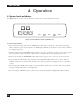
3.3 Placing the PQ-6 in Operation
When notified that the system operator has completed the system configuration, you can power on the PQ-6
PLUS (RO) (and all other cabled-through devices) using the following procedure:
A. Plug the power supply into the AC line.
B. Place the AC power switch on the attached printer in the “ON” position and place the printer into
“on-line” mode. The DTR indicator should light.
C. The LINE SYNC indicator should light as soon as communications with the host are established. The PQ-6
PLUS (RO) should now be exercised online to verify the operational readiness. Simply execute a print
comand.
M
ALFUNCTION RECOVERY PROCEDURES
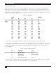
Table 3-8 describes the recovery procedures you can use if the machine malfunctions.
Table 3-8. Recovery Procedures.
Indicator Condition Probable Cause Recovery Action