
Network Router User Manual

PQ-6 PLUS (RO)
11
Installing a Centronics compatible printer
Connect the 6-pin connector from the power supply to the 6-pin connector on the back of the PQ-6 PLUS
(RO). Do not plug it into the AC outlet at this time.
Place the large jumper strip at P3, in the “A-B” position for parallel output.
The Centronics DB25 pinout is a standard DB25 to Centronics cable (Black Box part number EYN600) that
connects the PC to the printer. This cable’s pinning is shown in Table 3-3.
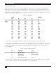
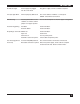
Table 3-3. Centronics to RS-232 Cable Wiring.
Pin No. Signal Source Description
1 Strobe PQ-6 PLUS (RO) Data strobe pulse to printer.
2 Data 1 PQ-6 PLUS (RO)
3 Data 2 PQ-6 PLUS (RO) 8 bits of parallel data.
4 Data 3 PQ-6 PLUS (RO)
5 Data 4 PQ-6 PLUS (RO)
6 Data 5 PQ-6 PLUS (RO)
7 Data 6 PQ-6 PLUS (RO)
8 Data 7 PQ-6 PLUS (RO)
9 Data 8 PQ-6 PLUS (RO)
10 Acknlg Printer Indicates data received and ready to accept other
data.
11 Busy Printer Indicates printer cannot receive data.
12 Paper End Printer Indicates out of paper.
13 Select Printer Indicates printer is selected and ready to receive
data.
14 Auto Feed PQ-6 PLUS (RO) When this signal is low (Jumper J1), the paper is
automatically fed one line after printing. This
signal does not apply to all printers.
15 Fault Printer Indicates a printer fault condition such as out of
paper.
16 Input PQ-6 PLUS (RO) Clears the printer buffer and initializes the logic.
18, 19, Ground PQ-6 PLUS (RO) Logic ground.
23, 25
Connect the Centronics printer cable to the DB25 connector at the back of the PQ-6 PLUS (RO). Locate
SW1 and set switch option 3 (position 2) to the “OFF” position.
3.1.2 P
OWER AND GROUNDING OF PQ-6 PLUS (RO)
Plug the power supply into a suitably grounded AC receptacle.