
Network Router User Manual

PQ-6 PLUS (RO)
10
Installing an RS-232 Printer
Connect the 6-pin connector from the power supply to the 6-pin connector on the back of the PQ-6 PLUS
(RO). Remove the top cover of the PQ-6 PLUS (RO). Do not plug it into the AC outlet at this time. Locate
switch SW1 to set the baud rate and port configuration. Select the serial transmission speed (baud rate) for the
PQ-6 PLUS (RO) output port using the four switches labeled Rate 4, Rate 3, Rate 2, and Rate 1 on the printed
circuit board according to Table 3-1.
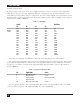
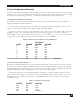
Table 3-1. Baud Rate.
Switch Baud Rate
S5 S6 S7 S8
OFF OFF OFF OFF 50
0=OFF OFF OFF OFF ON 75
1=ON OFF OFF ON OFF 110
OFF OFF ON ON 134.5
OFF ON OFF OFF 150
OFF ON OFF ON 300
OFFONONOFF600
OFF ON ON ON 1200
ON OFF OFF OFF 1800
ON OFF OFF ON 2000
ON OFF ON OFF 2400
ON OFF ON ON 3600
ON ON OFF OFF 4800
ON ON OFF ON 7200
ON ON ON OFF 9600
ON ON ON ON 19200
Select the port configuration for RS-232 serial operation by setting Opt 3 to the “ON” position.
Place the large internal jumper strip on P3 (P2 on boards with revision levels below C) in the “B-C” position
to select RS-232 output. Make sure that the cable to the PQ-6 PLUS (RO) is wired for DCE and contains wires
for pins 1, 2, 3, 7, and 20, connecting at the PQ-6 PLUS (RO) with a male DB25 connector. The signals are
shown in Table 3-2.
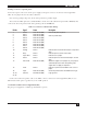
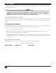
Table 3-2. Signals on the DCE cable.
Pin Signal Name Source
1 Chassis Ground —
2 Receive Data Printer
3 Transmit Data PQ-6 PLUS (RO)
7 Signal Ground —
20 Data Terminal Ready Printer
Place the supported printer close to the PQ-6 PLUS (RO). Connect the printer RS-232 cable to the DB25
connector on the back panel of the PQ-6 PLUS (RO). Proceed to Section 3.2.3.