
Specifications


724-746-5500 | blackbox.com
Page 16
Black Box
4. OPERATION
Once the ME670A is properly configured and installed, it should operate transpar-
ently—as if it were a standard cable connection. Operating power is derived from the
data and control signals; there is no “ON/OFF” switch. This chapter describes reading
the LED status monitors, powering-up and using the built-in V.52 and V.54 test modes.
4.1 FRONT PANEL SWITCHES
During normal operation, both front panel switches should be in the “normal” center
position. To operate a test mode, see
“V.54 Test Modes” on page 16.
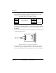
4.2 LED STATUS MONITORS
The ME670A features 2 front panel LEDs that indicate the condition of the V.52 and
V.54 test modes.
figure 13 on page 15 shows the location of each LED. “V.54 Test
Modes” describes each LED’s function in more detail.
4.3 V.54 TEST MODES
The ME670A offers two V.54 test modes to evaluate the condition of the modems and
the communication link. These tests can be activated physically from the front panel,
or via the RS-232 interface. Note: V.54 test modes on the ME670A are available for
point-to-point and 4-wire applications only.
Local Analog Loopback (LAL)
The Local Analog Loopback (LAL) test checks the operation of the local ME670A, and
is performed separately on each unit. Any data sent to the local ME670A in this test
mode will be echoed (returned) back to the user device. For example, characters
typed on the keyboard of a terminal will appear on the terminal screen. To perform a
LAL test, follow these steps:
1. Activate LAL. This may be done in one of two ways: First, by moving the front
panel toggle switch DOWN to “LAL”. Second, by raising pin 18 on the RS-232
interface (Note: Make sure DIP switch SW2-8 is OFF). Once LAL is activated,
the ME670A transmit output is connected to its own receiver. The “test” LED
should be lit.
2. Verify that the data terminal equipment is operating properly and can be used for
a test. If a fault is indicated, call a technician or replace the unit.
3. Perform a BER (bit error rate) test on each unit. If the BER test equipment indi-
cates no faults, but the data terminal indicates a fault, follow the manufacturer’s