
Specifications


724-746-5500 | blackbox.com
Page 13
Installation
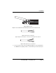
is too small or too large for our strain relief, please contact our technical support.
We have strain relief assemblies to accommodate most cable diameters.
Figure 10. Strain Relief Diagram
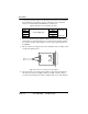
7. Insert the strain relief assembly with the wire going through it into the slot in the
bottom half of the modem case and set it into the recess in the case.
Figure 11. Recess Case with Strain Relief Assembly Diagram
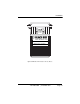
8. Bend the top half of the case as necessary to place it over the strain relief
assembly. Do not snap the case together yet.
Figure 12. Closing ME670A Chassis
XMT G RCV
XMT G RCV