
Specifications


724-746-5500 | blackbox.com
Page 12
Black Box
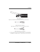
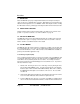
3. Connect the other pair of wires to the two RCV (receive) poles on the terminal
block. Ultimately, you will want to construct a two-pair crossover cable that
makes a connection with the two ME670As as shown below:
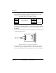
4. If there is a shield around the telephone cable it may be connected to “G” on the
terminal block. To avoid ground loops, we recommend connecting the shield at
the computer end only. A ground wire is not necessary for proper operation of
the ME670A.
5. When you finish connecting the wires to the terminal block, the assembly should
resemble the diagram below:
Figure 9. Two-Pair Crossover Cable Connection Diagram
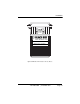
6. Place the 2 halves of the strain relief assembly on either side of the telephone
wire and press together very lightly. Slide the assembly so that it is about 2
inches from the terminal posts and press together firmly. If your cable diameter
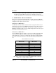
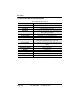
Table 10: Two-pair Crossover Cable Connections
XMT
To Shield (Optional)
RCV
One Pair
XMT RCV
G G
RCV XMT
One Pair
RCV XMT
XMT G RCV