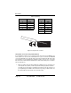
ME670A Multi-Function Line Driver, DB25
Black Box TABLE OF CONTENTS 1. Overview ...........................................................................................................5 1.1 Features ................................................................................................5 1.2 Description ............................................................................................5 2. Configuration ....................................................................................................6 2.
RADIO FREQUENCY INTERFERENCE STATEMENTS FEDERAL COMMUNICATIONS COMMISSION AND INDUSTRY CANADA RADIO FREQUENCY INTERFERENCE STATEMENTS This equipment generates, uses, and can radiate radio-frequency energy, and if not installed and used properly, that is, in strict accordance with the manufacturer’s instructions, may cause interference to radio communication.
Black Box 1. OVERVIEW This section provides a gerneral list of features and a description of the Black Box product. 1.1 FEATURES • Switch-selectable carrier control • Synchronous or asynchronous operation • No AC power or batteries required • Data rates to 38.4 Kbps • Distances to 12 miles (19.2 km) • Point-to-point or multipoint operation • Full or half duplex operation • Internal, external or received loopback clocking • V.54 loopback tests and V.
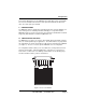
Configuration Housed in an ABS plastic case, the ME670A comes with either a male or female DB25 connector and both an RJ-11/RJ-45 combo jack and terminal blocks with strain relief. The combo jack is pre-installed. 2. CONFIGURATION The ME670A is simple to install and is ruggedly designed for excellent reliability: just set it and forget it. The following instructions will help you set up and install the ME670A properly.
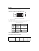
Black Box 2.2 CONFIGURATION SWITCH SETTINGS The ME670A has two sets of eight switches, yielding 16 total DIP switches. The two sets will be referred to as SW1 and SW2. As Figure 2 shows, the orientation of all DIP switches is the same with respect to “ON” and “OFF” positions. ON DHS-8 1 2 3 4 5 6 7 8 OFF OFF Figure 2. Close up of cofiguration switches 2.3 SWITCH SET SW1 The DIP switches on SW1 set data rate, clock source, async./sync. mode and carrier control method.
Configuration Table 3: Data Rate Setting SW1-1 SW1-2 SW1-3 SW1-4 Setting (Kbps) On Off On Off On Off On Off On Off Off On On Off Off On On On On On Off Off Off Off Off On On On On On On On On Off Off Off 2.4 3.6 4.8 7.2 9.6 14.4 19.2 28.8 38.4 SW1-5 and SW1-6: Clock Source Switches SW1-5 and SW1-6 are set in combination to determine the clock source for the ME670A.
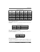
Black Box hardware handshaking applications. Note: SW1-8 must be “ON” in all 2-wire applications. Table 6: Carrier Control Method SW1-8 Setting Off On Constantly on Controlled by RTS 2.4 SWITCH SET SW2 The DIP switches on SW2 set word length, extended signaling rate, RTS/CTS delay, 2-wire/4-wire and V.52/V.54 tests. The factory default settings for Switch Set SW2 are summarized in the table below.
Installation 3. INSTALLATION Once the ME670A is properly configured, it is ready to connect to your system. This section tells you how to connect the ME670A to the twisted pair and RS-232 interfaces. 3.1 CONNECTION TO THE TWISTED PAIR INTERFACE The ME670A supports data-only communication between two RS-232 devices at distances to 12 miles (19.2) and data rates to 38.4 Kbps. There are two essential requirements for installing the ME670A: • These units work in pairs.
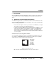
Black Box Table 9. Plug Wiring RJ-11 Signal RJ-45 Signal 1 2 3 GND* RCV* XMT 1 2 3 N/C GND* 4 5 6 XMT RCV GND* 4 5 6 7 8 RCVXMT XMT RCV GND* N/C Figure 4. Inserting flathead screwdriver Twisted Pair Connection Using Terminal Blocks If your application requires you to connect two pairs of bare wires to the ME670A, you must open the case to access the terminal blocks. For your convenience, the ME670A comes standard with a RJ-11/RJ-45 combo jack and a terminal block with strain relief.
Installation Figure 5. ME670A opened Strip the outer insulation from the twisted pairs about one inch from the end. Figure 6. Twisted pair pre-modification Figure 7. Strip back the insulation on each of the 2 twisted pair wires about.25”. Figure 8. Twisted pair wires post modefication 2. Connect one pair of wires to the two XMT (transmit) poles on the terminal block. The ME670A is not polarity sensitive, so either wire may connect to either pole. 724-746-5500 | blackbox.
Black Box 3. Connect the other pair of wires to the two RCV (receive) poles on the terminal block. Ultimately, you will want to construct a two-pair crossover cable that makes a connection with the two ME670As as shown below: Table 10: Two-pair XMT XMT G RCV RCV Crossover Cable Connections To Shield (Optional) RCV RCV G XMT XMT One Pair One Pair 4. If there is a shield around the telephone cable it may be connected to “G” on the terminal block.
Installation is too small or too large for our strain relief, please contact our technical support. We have strain relief assemblies to accommodate most cable diameters. XMT G RCV Figure 10. Strain Relief Diagram 7. Insert the strain relief assembly with the wire going through it into the slot in the bottom half of the modem case and set it into the recess in the case. XMT G RCV Figure 11. Recess Case with Strain Relief Assembly Diagram 8.
Black Box 9. Insert one captive screw through a saddle washer, then insert the entire piece through the hole in the DB-25 end of the case. Snap that side of the case closed. Repeat the process for the other side. This completes cable installation. 3.2 CONNECTION TO THE RS-232 INTERFACE Once you have connected the twisted pair wires correctly, simply plug the ME670A directly into the DB-25 port of the RS-232 device. After doing so, remember to insert and tighten the two captive connector screws.
Installation BERT LOOP 511/RDL NORMAL 511 LAL ME670A Multi-Function Line Driver S/N 123456 Figure 13. ME670A’s LED indicators and test switches 724-746-5500 | blackbox.
Black Box 4. OPERATION Once the ME670A is properly configured and installed, it should operate transparently—as if it were a standard cable connection. Operating power is derived from the data and control signals; there is no “ON/OFF” switch. This chapter describes reading the LED status monitors, powering-up and using the built-in V.52 and V.54 test modes. 4.1 FRONT PANEL SWITCHES During normal operation, both front panel switches should be in the “normal” center position. To operate a test mode, see “V.
Operation checkout procedures for the data terminal. Also, check the RS-232 interface cable between the terminal and the ME670A. Remote Digital Loopback (RDL) The Remote Digital Loopback (RDL) test checks the performance of both the local and remote ME670As and the communication link between them. Any characters sent to the remote ME670A in this test mode will be returned back to the originating device.
Black Box 4.4 POWER-DOWN Turn off the ME670A by simply removing it from the circuit or by turning off the terminal that is directly connected to the ME670A. Page 18 724-746-5500 | blackbox.
Compliance A. COMPLIANCE A.1 EMC • FCC Part 15, Class A • EN55022, Class A • EN ETSI 300 386 V1.3.3 A.2 LOW VOLTAGE DIRECTIVE (SAFETY) • UL 60950-1/CSA C22.2 No. 60950-1 • IEC/EN60950-1 A.3 RADIO AND TV INTERFERENCE (FCC PART 15) This device generates and uses radio frequency energy, and if not installed and used properly-that is, in strict accordance with the manufacturer’s instructions-may cause interference to radio and television reception.
Black Box B. BLACK BOX ME670A SPECIFICATIONS Table 12. ME670A Specifications Transmission Format Sync. and asyn., full or half duplex Transmission Line Unconditioned twisted pair 19-26 AWG Clocking Internal, external, or receive loopback Interfaces EIA RS-232, CCITT V.24 Data Rates 1.2, 1.8, 2.4, 3.6, 4.8, 7.2, 9.6, 14.4, 19.2, 28.8, 34.
Black Box ME670A C. BLACK BOX ME670A 724-746-5500 | blackbox.
Black Box ME670A Block Diagram D. BLACK BOX ME670A BLOCK DIAGRAM 724-746-5500 | blackbox.
ME670A version 1