
Installation manual


2. WIRING
2-3
2.1.3 CAN bus port
Every TZTBB has one CAN bus port (micro style connector). All TZT9/14 MUST be
connected to the same CAN bus backbone. However, the TZTBB and DRS (radar
sensor) CAN bus ports cannot be connected together. The TZTBB and DRS (radar
sensor) use “Ethernet Bridging” to link the DRS CAN bus and the TZTBB CAN bus
data. Refer to paragraph 2.2.1 for more information. Note that the TZTBB CAN bus
port is not powered unless external power is applied to the FRUDD-18AFFM-L180 ca-
ble of MULTI port and must be connected to a properly configured CAN bus network.
What is CAN bus?
CAN bus is a communication protocol that shares multiple data and signals through a
single backbone cable. You can simply connect any CAN bus devices onto the back-
bone cable to expand your network onboard. With CAN bus, IDs are assigned to all
the devices in the network, and the status of each sensor in the network can be de-
tected. All the CAN bus devices can be incorporated into the NMEA2000 network. For
detailed information about CAN bus wiring, see “Furuno CAN bus Network Design
Guide” (Type: TIE-00170) on Tech-Net.
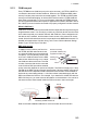
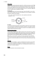
DRS radar sensor
In addition to the CAN bus port found on
the TZTBB, all DRS radar sensors have
one powered CAN bus port (terminal strip
connector). You may directly connect vari-
ous Furuno CAN bus sensors to the DRS
radar sensor without having to run a sepa-
rate CAN bus cable to the mast. The total
number of sensors that can be connected
to the CAN bus DRS port without external
power connection depends on power consumption. The DRS can supply up to 1 amp
(20LEN) to the DRS CAN bus network. Note that the CAN bus network connected to
the DRS is its own independent CAN bus backbone and needs to be terminated at
both ends by a terminating resistor. A 120 Ohm resistor is standard supply with the
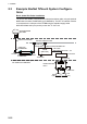
DRS to terminate the CAN bus. For example, if you install a SC-30/WS-200 with the
DRS CAN bus port, you must have two terminators on the backbone. One can be at
the sensor and the other located inside the DRS as shown in the inset at right.
Refer to the DRS Installation Manual for more information about connection.
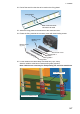
Resistor assembly
(120 OHM-1007#24-L50,
supplied with DRS)
Twisting and
soldering
White
Blue
CAN bus cable
WS-200 SC-30
In the above example, the terminating resistors are
necessary at DRS and SC-30.