
Installation manual


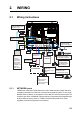


2. WIRING
2-2
2.1.2 MULTI port
Use the cable assembly FRUDD-18AFFM-L180 (supplied, 2 m)
for the event switch, external buzzer, speed alarm and the power
for CAN bus. This cable has an 18-pin connector. For example, a
MOB contact closure input may be connected to pin 15 and 11*.
*Note that any TZTBB interfaces to virtually any MOB system or
event switch (point save) contact closure signal using these pins.
Pin No. Color Function Remark (Port No.)
18 Light green NET-C IN (0V) CAN bus Power IN. When 12V DC power is
applied to these pins, the CAN bus port will be
powered (up to 1 ampere).
17 Pink NET-S IN (+12V IN)
16 Purple Shield
15 White BUZZER or EVENT IN
External Buzzer Output or MOB/Event Input
(Contact Closure)
14 Gray SPEED-ALARM C Speed alarm contact. Can trigger an external
alarm or device when speed exceeds the limit
specified.
13 Yellow SPEED-ALARM H
12 Black/White +12V External buzzer power ONLY (100 mA max.)
11 Black GND GND for Event/MOB Input
10 Blue/White - For debug
9Blue -
8Green/White -
7Green -
6 Orange/White -
5Orange GND
4 Brown/White DC_N
3 Brown PWR_SW
2Red/White GND
1Red GND
7
12
16
17
13
8
3
1
4
9
14
18
15
10
5
2
6
11