Installation Manual Multi Function Display Black Box Type TZTBB SAFETY INSTRUCTIONS ................................................................................................ i SYSTEM CONFIGURATION ........................................................................................... ii EQUIPMENT LISTS........................................................................................................ iii 1. MOUNTING..............................................................................
SAFETY INSTRUCTIONS The installer must read the safety instructions before attempting to install the equipment. WARNING Indicates a potentially hazardous situation which, if not avoided, could result in death or serious injury. CAUTION Indicates a potentially hazardous situation which, if not avoided, may result in minor or moderate injury.
SYSTEM CONFIGURATION Basic configuration is shown with solid line. RADAR SENSOR DRS4A/DRS6A/DRS12A/DRS25A RADAR SENSOR DRS2D/DRS4D OR POWER SUPPLY UNIT* PSU-017 POWER SUPPLY UNIT* PSU-012/PSU-013 FAR-2xx7 series 12-24 VDC 12-24 VDC FCV-1150, BBDS1, DFF series FA-30/50 NAVpilot-700 HUB -101 SC-30 GP-330/WS-200 FI-5002 FAX-30 IP Camera FUSION-Link equipment FI-50, etc.
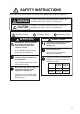
EQUIPMENT LISTS Standard supply Name Processor Unit Switch Box Installation Materials Accessories Spare Parts Type MPU-002 PSD-002 Code No. - Qty 1 1 CP19-01700 000-022-530 1 FP19-01801 SP19-01401 001-205-650 001-205-630 1 1 Remarks CP19-01701 Fuses Optional supply Name Joint Box NMEA2000Interface Unit NMEA Data Converter Network HUB Junction Box Rectifier CAN bus Cable Assy. DVI-D Cable Assy. External Buzzer Network (LAN) Cable Type TL-CAT-012 Code No.
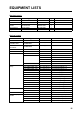
EQUIPMENT LISTS Name CAN bus Connector MJ Cable Assy. Operator’s Manual iv Type SS-050505-FMFTS001 NC-050505-FMFTS001 LTWMC-05BMMTSL8001 LTWMN-05AMMTSL8001 LTWMC-05BFFTSL8001 LTWMN-05AFFTSL8001 FRU-0505-FF-IS MJ-A6SPF0016-005C OME-44700-* OMJ-44700-* Code No.
1. MOUNTING 1.1 Mounting Considerations When selecting a mounting location for TZTBB, keep the following in mind: • The temperature at the mounting location shall be between -15°C and +55°C (wireless LAN: 0°C and +55°C). • The humidity at the mounting location shall be 93% or less at 40°C. • Locate the unit away from exhaust pipes and ventilators. • The mounting location should be well ventilated. • Mount the unit where shock and vibration are minimal (comply with IEC 60945 Ed.4).
1. MOUNTING 1.3 Switch Box The switch box PSD-002 is designed to be flush mounted on a flat bulkhead. Refer to the outline drawing for mounting dimensions. Procedure 95±1 1. Make a cutout in the mounting location as shown below. 86±1 R10 Cutout dimensions 2. Insert the sponge to the switch box from the rear side. 3. Set the unit to the cutout and fix the flush mount fixture from the rear side with two screws. 4. Tighten the wing bolts to fasten the switch box. 5.
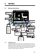
2. WIRING 2.1 Wiring Instructions MOD-WPAS0001-030+ (Supplied, 3 m) DVI-OUT0 DVI-D/D S-LINK cable (Supplied, 24 pin, 0.5 m) LINE OUT Ground terminal TO: Ship's ground (IV-8sp.
2. WIRING 2.1.2 MULTI port Use the cable assembly FRUDD-18AFFM-L180 (supplied, 2 m) for the event switch, external buzzer, speed alarm and the power for CAN bus. This cable has an 18-pin connector. For example, a MOB contact closure input may be connected to pin 15 and 11*. *Note that any TZTBB interfaces to virtually any MOB system or event switch (point save) contact closure signal using these pins. Pin No.
2. WIRING 2.1.3 CAN bus port Every TZTBB has one CAN bus port (micro style connector). All TZT9/14 MUST be connected to the same CAN bus backbone. However, the TZTBB and DRS (radar sensor) CAN bus ports cannot be connected together. The TZTBB and DRS (radar sensor) use “Ethernet Bridging” to link the DRS CAN bus and the TZTBB CAN bus data. Refer to paragraph 2.2.1 for more information.
2. WIRING NMEA0183 equipment To connect an NMEA0183 equipment to TZTBB, use the CAN bus network via the optional NMEA data converter IF-NMEA2K2 (or IF-NMEA2K1). This NMEA connection can accept a baud rate of 4800 or 38400. Heading input to TZTBB allows functions such as Radar Overlay and course stabilization (North up, Course up, etc.) in the radar operating modes. The NMEA0183 heading refresh rate needs to be 100 ms in order for any radar function to work properly.
2. WIRING 2. Attach the DVI-D, Video composite and Audio cable connectors to their respective ports. DVI-D OUT0 Audio OUT Video IN 1/2 3. Set the waterproofing gasket to the boot cover then pass the cables through the boot cover. 4. Fasten the boot cover with four binding screws. 5. Attach the fixing plate to the boot cover. 6. Pass the cables through appropriate holes in the gasket. The largest hole is for the DVI-D cable. 7. Set the cable adapter to the entrance of the boot cover. 8.
2. WIRING 10. Fix the cables to the cable clamp with cable ties (2 pcs. each). Attach a cable tie at the base of waterproofing tube. Note: Cable ties are necessary for waterproofing. Do not fail to attach them. Cable ties for fixing Cable ties for waterproofing Add a tie for waterproofing Fix the cables with cable ties Bottom side 11. Pass the opposite end of the DVI-D cable (connected at step 1) through the outside entrance of the connector cover. 12.
2. WIRING 22. Peel off the seal from the slots to be used on the fixing plate2. Fixing plate2 Peel off the seal from the slots to be used 23. Attach the fixing plate2 to the entrance of the connector cover. 24. Fasten the fixing metal to the connector cover with three binding screws. Binding screw (6 pcs.) Binding screw (3 pcs.) Connector cover Fixing plate 1 Gasket Fixing plate 2 Fixing metal 25. Fix the cables to the cable clamp with cable ties (2 pcs. each).
2. WIRING Video input TZTBB can use regular analog video inputs (PAL or NTSC) that connect to the TZTBB directly or use IP cameras that connect directly to the network HUB. IP cameras can be seen by all TZTBB connected to the NavNet TZtouch network, unlike analog video that can be viewed only on the equipment where the source is connected. Additionally some IP cameras can be controlled from TZTBB.
2. WIRING 2.2 CAN bus/NMEA0183 Data Conversion 2.2.1 Connection with DRS radar sensor All DRS radar sensors have one CAN bus port (Terminal Block connector). You can directly connect Furuno CAN bus sensors to the DRS radar without having to run another CAN bus cable up the mast. In this case, each separate CAN bus network (the DRS CAN bus and the ship CAN bus) will be “Bridged” together via the Ether Network. Note that the TZTBB and DRS CAN bus ports must not be connected together.
2. WIRING 2.2.2 CAN bus (NMEA2000) input/output PGN Input PGN No. 01. 02. 04. 06. 07. 08. 11. 12. 13. 14. 15. 16. 17. 18. 19. 20. 21. 22 23. 24. 25. 26. 27. 28. 29. 30. 31. 32. 33. 34. 35. 36. 37. 38. 39. 40. 41. 42. 43. 44. 45. 46. 47. 48.
2. WIRING Output PGN The CAN bus output PGN setting (found under the [Initial Setup] menu) is global to the network. Note that only one TZTBB will output CAN bus data on the network at a time: the TZTBB which is powered ON first. If that display is turned OFF, another will take its place to output the data. No. 01. PGN 059392 Description ISO Acknowledgement 02. 059904 ISO Request 04. 060928 ISO Address Claim 05. NMEA-Request group function 06. 126208 07. 08. 09. 126464 12. 13.
2. WIRING 2.3 Example NavNet TZtouch System Configurations Basic plotter/fish finder installation The Furuno GP-320B is connected to the CAN bus backbone cable, using the optional NMEA data converter IF-NMEA2K2 (or IF-NMEA2K1). The DFF1/3 network sounder is connected to the LAN port of the TZTBB using the standard supply cable MOD-WPAS0001-030+(3 m) and a junction box TL-CAT-012.
2. WIRING Basic plotter/radar/fish finder installation This is a single station plotter/radar/fish finder installation. Connection of multiple sensors, such as DFF3 and DRS series, requires the optional Ethernet Hub HUB-101. Also, the power supply unit PSU-012, PSU-013 or PSU-017 is required for the connection with DRS series radar sensor. Radar Sensor DRS2D/4D, ETC.
2. WIRING This page is intentionally left blank.
3. SETTING UP THE EQUIPMENT This chapter shows you how to set up your system according to the equipment you have connected. You can do almost all operations on this equipment by just touching the display, following the instructions below. Touch control description The touch control depends on the screen type. The basic operations to use at the installation setting are in the table shown below. Operation by a finger Operating by a finger Function Tap • Select a menu item. • Select an object.
3. SETTING UP THE EQUIPMENT About menu operations The following procedure shows how to use the menu system. 1. Press the key on the switch box to turn the power on. The chart plotter display appears after the start-up screen appears. 2. Tap the Home icon ( ) at the top right-hand corner of the screen. The menu icon bar appears on the menu selection display. Menu icon bar This icon appears only when fusion equipment is connected. 3. Select (tap) the Menu icon ( 350 0 ) to open the main menu.
3. SETTING UP THE EQUIPMENT Icon Description This icon means that a menu item has some options. Touch it to show the option window (pull-down list). Touch the menu item with this icon to display the software keyboard, to enter alphanumeric data. For details, see “How to use the software keyboard” shown below. • Shows a sub menu. • Switches a functions ON or OFF. • Selects a color. Drag the circle icon to adjust the setting value. 40 6.
3. SETTING UP THE EQUIPMENT 3.1 How to Set Time Zone, Language and Units Before setting up your equipment, select the time zone, language and units to use on your equipment as shown below. 1. Tap the Home icon, then select [Menu] icon ( ) from the menu icon bar. 2. Select [General] on the main menu to show the [Menu General] sub menus. 3. To use local time (instead of UTC), do this step and step 4. Otherwise, skip to step 5. Select [Local Time Offset] to show the option window.
3. SETTING UP THE EQUIPMENT [Menu Units] sub menus Menu item Options [Bearing Display] [True], [Magnetic] [True Wind Calculation Ref- [Ground], [Surface] erence] [Position Format] [DDD°MM.mmmm’], [DDD°MM.mmm’], [DDD°MM.mm’], [DDD°MM’SS.ss”], [DDD.dddddd°], [Loran C], [MGRS] [Loran C Station & GRI] [GRI] Select GRI code. [Master] [First (Second) Slave] X: Upolu Point, Y: Kure Island [Correction First (Second) Enter a position offset to refine Loran C Slave] position.
3. SETTING UP THE EQUIPMENT Menu Initial Setup Menu item [Boat Length] [Longitudinal GPS Position] [Lateral GPS Position (-Port)] [Boat Icon] [Size of Static Icon] [Depth Display] [Transducer Draft Source] [Keel Draft] [Average Boat Speed] [Nav Data Maximum Depth] Description Options (setting range) Set the length of your boat. 5.0 to 9,999 ft Enter the GPS antenna positioning bow-stern (Longitudinal) Origin and port-starboard (Lateral) position from the origin.
3. SETTING UP THE EQUIPMENT Menu Initial Setup (Fuel) Menu Item Description [Number of Tank] Select the number of fuel tanks on your boat. Options (setting range) [1], [2], [3], [4] [NickName Tank 1 to 4] Change the nickname for fuel tank 1 to 4. Manu Initial Setup (Use Fuel Tank for calculations) Menu Item [Tank 1 to 4] Description Select the tanks to calculate the fuel consumption.
3. SETTING UP THE EQUIPMENT Menu Initial Setup (Data Damping) Menu item Description Options (setting range) [COG & SOG] Set data damping time. The lower the set- 0 to 59 seconds ting the faster the response to change. [Heading] [Speed Through Water] [Wind Speed & Angle] [Rate of Turn] Menu Initial Setup (Browser Installation) Menu item [FAX30 Browser] [FA30 Browser] [FA50 Browser] 3.3 Description Option (setting range) Show the Facsimile Receiver FAX-30 display. Show the AIS Receiver FA-30 display.
3. SETTING UP THE EQUIPMENT 2. Drag the [Menu Radar] sub menus to find the menu item [Radar Initial Setup]. Title Menu item [Antenna Rotation] [Antenna Heading Align] [Main Bang Suppression] [Antenna Height] [Antenna Longitudinal Position] [Antenna Lateral Position (Port)] Others Menu Radar (Radar Initial Setup) Description Select the speed of antenna rotation. See the topic of “How to align the antenna heading” shown on the next page.
3. SETTING UP THE EQUIPMENT How to align the antenna heading You have mounted the antenna unit facing straight ahead in the direction of the bow. Therefore, a small but conspicuous target dead ahead visually should appear on the heading line (zero degrees). In practice, you will probably observe some small bearing error on the display because of the difficulty in achieving accurate initial positioning of the antenna unit. The following adjustment will compensate for the error. 1) Select a range between 0.
3. SETTING UP THE EQUIPMENT 3.4 How to Set up the Sounder If you have a sounder (BBDS or DFF series), set up the sounder as shown in this section. Drag the main menu to select [Sounder]. You can confirm the actual sounder display on the left-hand side of the screen while setting up. Drag the [Menu Sounder] sub menus to select [Sounder Initial Setup].
3. SETTING UP THE EQUIPMENT 3.5 Wireless LAN Setting Note: Some TZTBBs are not equipped with the wireless LAN. The TZTBB can be configured to create a wireless network (“Ad Hoc”) or to connect to an existing wireless network. Connecting to an existing wireless network is very useful if you already have an Access Point setup on your boat, especially if you have Internet available. Simply connect the TZTBB and your smartphone or tablet to the existing wireless network.
4. HOW TO INSTALL THE HDD 4.1 Hard Disk Drive (HDD) An HDD (local supply) can be installed inside the processor unit. The usable HDD size is 90 x 134 x 20 mm. Install the HDD inside the processor unit as follows. Procedure 1. Unfasten the binding screws (M3x10, 8 pcs.) to remove the cover from the rear panel. Binding screw (8 pcs.) 2. Unfasten the binding screws (M4x8, 4 pcs.) to remove the HDD casing. Binding screw (4 pcs.
4. HOW TO INSTALL THE HDD 3. Unfasten the binding screws (M4x8, 4 pcs.) to remove the lid of the HDD casing. Binding screw (4 pcs.) Lid HDD HDD casing 4. Set the HDD into the casing with correct orientation. 5. Fasten the lid to the HDD casing with four binding screws. 6. Connect the USB plug to the port of the processor unit with the HDD cable. Connector (Processor unit) USB plug 7. Set the HDD casing into the processor unit and fasten it with four binding screws. 8.
INSTALLATION MATERIALS ACCESSORIES SPARE PARTS UNIT OUTLINE 000-164-608-10 FRUDD-18AFFM-L180 000-177-282-10 DVI-D/D S-LINK 0.5M 001-205-650-00 FP19-01801 000-176-350-1* L293XW230XH18 100-375-230-10 19-031-1563-0 001-205-630-00 SP19-01401 000-022-528-00 PSD-002-* 000-022-525-00 MPU-002-* 1 1 1 (略図の寸法は、参考値です。 DIMENSIONS IN DRAWING FOR REFERENCE ONLY.
ᢙ㊂ 3 6; ↪ㅜ㧛⠨ 4'/#4-5 (75' .#$'. 㩕㨷㨺㩇㩨㩔㩢㩙㨺㩂 -01$ 0 㩓㩖㩨 0 $.+0& 5'#. 0 㩖㩨㩡㨼㩧㩎㩨㩆㨺㩣 0 *#0)'4 9#5*'4 㩔㩧㩀㩨㨺㩦㨹㩆㨶㨺 ฬޓޓ⒓ 0#/' ⇛ޓޓ࿑ 176.+0' %1&' 01 %1&' 01 %1&' 01 %1&' 01 41*5 ဳฬ㧛ⷙᩰ &'5%4+26+105 ᢙ㊂ 3 6; ↪ㅜ㧛⠨ 4'/#4-5 㧲㨁㧾㨁㧺㧻ޓ㧱㧸㧱㧯㨀㧾㧵㧯ޓ㧯㧻ޓ㧚㧘㧸㨀㧰 㧔⇛࿑ߩኸᴺߪޔෳ⠨୯ߢߔ&ޓޕ+/'05+105 +0 &4#9+0) (14 4'('4'0%' 10.
/27 ).#55 67$' (75' 㩕㨷㨺㩇㩨 (75' ).#55 67$' 6;2' 㩕㨷㨺㩇㩨 176.+0' ()$1 8 # 2$( ()$ # 8 # 2$( 5'65 2'4 8'55'. 4'/#4-5 %1&' 01 % 2 # 52#4' $& : $1: 01 2 㧔⇛࿑ߩኸᴺߪޔෳ⠨୯ߢߔ&ޓޕ+/'05+105 +0 &4#9+0)(ޓ14 4'('4'0%' 10.; 㧕 ဳᑼ 㩄㨺㩎㩨⇟ภ߇㧞Ბߩ႐วޔਅᲑࠃࠅᲑߦઍࠊࠆㆊᷰᦼຠߢࠅޔ߅ߥޓޕߔ߹ߡߞ߇߆ࠄߜߤޔຠ⾰ߪ ᄌࠊࠅ߹ߖࠎޕ 691 6;2'5 #0& %1&'5 /#; $' .+56'& (14 #0 +6'/ 6*' .19'4 241&7%6 /#; $' 5*+22'& +0 2.#%' 1( 6*' 722'4 241&7%6 37#.
25/Dec/2012 Y.
21/Dec/2012 Y.
,CP ; 0+5*+;#/# Yoshihir o Nishiya ma 電子署名者 : Yoshihiro Nishiyama DN: cn=Yoshihiro Nishiyama, c=JP - 日本, o=FURUNO ELECTRIC Co., Ltd., ou=Technical Documentation Section, email=yoshihiro.nishiyama@furuno.co.jp 日付 : 2013.01.
& % $ # &2;% / $((/ O ࠕࠞ ࠢࡠ ࠪࡠ %#$.' 9 /+0+ 2.7) O ࠕࠝ 4'& $.9*6 $.7 / 2//2 2.7) Ǿ , , %1#: %#$.' ǡ %1#: %#$.' ǡ 4%# 4%# 75$ %#$.' 4%# 4%# # 6;2' 8+&'1 75$ , 8+&'1 , , , 75$ , 75$ )0& 8A176A2 52''&A#.#4/ # 52''&A#.#4/ $ $7<
The paper used in this manual is elemental chlorine free. ・FURUNO Authorized Distributor/Dealer 9-52 Ashihara-cho, Nishinomiya, 662-8580, JAPAN All rights reserved. Printed in Japan A : JAN . 2013 C : MAR . 28, 2013 Pub. No.