
Specifications

Link Interfaces Reference
25
25
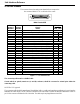
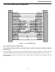
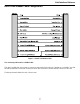
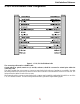
V.11 & X.21 Link Pinouts
The pinouts described here correspond to the V.11/X.21 mode for a Universal WAN router.
Note: A DB25 to DB15 pin converter will be required to connect to V.11/X.21 service.
Contact
Number
X.21
Circuits
Reference
Circuit
Name
Direction
To From
DCE DCE
1 Protective Ground NA
2 T (A) Transmitted Data (A) X
3 C (A) Control (A) X
4 R (A) Received Data (A) X
5 I (A) Indication (A) X
6 S (A) Signal Element Timing (A) X
7 ----------
8 Ground Signal Ground NA
9 T (B) Transmitted Data (B) X
10 C (B) Control (B) X
11 R (B) Received Data (B) X
12 I (B) Indication (B) X
13 S (B) Signal Element Timing (B) X
14 ----------
15 ----------
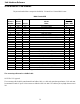
Figure 2 - 7 V.11 Link Pinouts
The connecting cable must be a shielded cable.
Circuits which are paired (contain an (A) and (B) reference) should be connected to twisted pairs within the
connecting cable.
NOTE For U.K. Approval:
The connecting cable should be manufactured from Belden Cable, or a cable with equivalent specifications. Each end must
be terminated in a male 15 pin X.21 connector as defined in ISO-4903 1989, but one end of the cable must have UNC-4-40
screws and the other end must have M3 screws. The cable may be any length between 0 and 5M.