
Specifications

Link Interfaces Reference
24
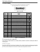
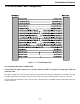
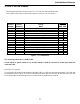
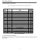
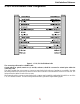
V.24 & RS232C Link Pinouts
The pinouts described here correspond to the RS232/ V.24 mode for a Universal WAN router.
DB25 Female DTE
Contact
Number
CCITT
Circuit
Number Circuit
Circuit
Name
Direction
To From
DCE DCE
1 101 AA Protective Ground NA
2 103 BA Transmitted Data X
3 104 BB Received Data X
4 105 CA Request to Send X
5 ----------
6 107 CC Data Set Ready X
7 102 AB Signal Ground NA
8 109 CF Received Line Signal Detector (CD) X
9 ----------
10 ----------
11 ----------
12 ----------
13 ----------
14 ----------
15 114 DB Transmit Signal Element Timing (DCE Source) X
16 ----------
17 115 DD Receive Signal Element Timing (DCE Source) X
18 141 Local Loopback X
19 ----------
20 108.2 CD Data Terminal Ready X
21 ----------
22 125 CE Ring Indicator X
23 ----------
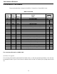
24 113 DA Transmit Signal Element Timing (DTE Source) X
25 ----------
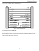
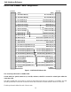
Figure 2 - 6 RS232 Link Pinouts
The connecting cable must be a shielded cable.
NOTE For U.K. Approval:
The connecting cable should be manufactured from Belden Cable, or a cable with equivalent specifications. Each end must
be terminated in a male 25 pin X.21 bis connector as defined in ISO-2110 1989. The cable may be any length between 0 and
5M.