
Specifications

19
2 Link Interface Reference
Pinout Information
The router is manufactured with four different WAN link modules: V.35, LXT411 CSU/DSU, Universal WAN or T1/E1.
The type installed may be determined from the label on the WAN link output connector.
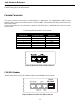
V.35 Module:
The V.35 link interface is provided as a DB25 connector on the back of the bridge/router, so an interface converter is needed
to convert to the standard V.35 connectors.
When connecting two bridge/routers back-to-back without modems, a null-modem cable is required to crossover the pins on
the links. Crossing over the pins allows two bridge/routers both configured as DTE interfaces to be connected together.
With this configuration, both bridge/routers will provide clocking for the links, and each bridge/router must have a link
speed defined.
UNIVERSAL WAN Module:
WARNING: ensure that the connector cable used with the Universal WAN interface module has the correct pinouts for the
operational mode selected for the interface (V.11, V.35, RS232, or EIA530). Using the incorrect cable connector for the
operational mode selected may cause permanent damage to the interface module.
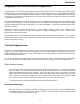
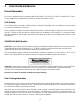
The Universal WAN Interface module in this router may be configured to operate in one of four modes: V.11/X.21, V.35,
RS232/V.24, or RS530/RS422. The interface connector for all types is a standard DB25 pin female connector.
13
1
25
14
WARNING: ensure that the connector cable used with the Universal WAN interface module has the correct pinouts for the
operational mode selected for the interface (V.11X.21, V.35, RS232/V.24, or RS530/RS422). Using the incorrect cable
connector for the operational mode selected may cause permanent damage to the interface module.
Pinouts for each mode of operation are listed on the pages following.
Link Clocking Information
The link interface on the router acts as a DTE device, this means that it may be directly connected to DCE devices with the
DCE devices providing the clocking for the link. The link speed is controlled by the DCE device. Setting the link speed on
the router will not result in a speed change on the link.
Some DCE devices allow the DTE devices connected to them to supply a clock signal which is then routed back to the
transmit clock pins (external clock pins) on the DCE interface. This clock is then received by the router link interface. By
using this method, the router may be in control of the link speed. The link speed may also be controlled by the router when
a null-modem cable is used to connect two routers in a back-to-back configuration.