LHC201A LHC202A Pure Networking™ Fast Ethernet Media Converters Link a 10/100BASE-TX segment to a 100BASE-FX BOX segment on your network, and BLACK extend the 328 foot (100 m) distance limit of copper-based Ethernet. ® Customer Support Information Order toll-free in the U.S.: Call 877-877-BBOX (outside U.S.
Trademarks Used in this Manual Trademarks Used in this Manual Black Box and the Double Diamond logo are registered trademarks of BB Technologies, Inc. Any other trademarks mentioned in this manual are acknowledged to be the property of the trademark owners. Page 2 724-746-5500 | blackbox.
FCC and IC RFI Statements FEDERAL COMMUNICATIONS COMMISSION AND INDUSTRY CANADA RADIO FREQUENCY INTERFERENCE STATEMENTS Class B Digital Device. This equipment has been tested and found to comply with the limits for a Class B computing device pursuant to Part 15 of the FCC Rules. These limits are designed to provide reasonable protection against harmful interference in a residential installation. However, there is no guarantee that interference will not occur in a particular installation.
NOM Statement Normas Oficiales Mexicanas (NOM) Electrical Safety Statement INSTRUCCIONES DE SEGURIDAD 1. Todas las instrucciones de seguridad y operación deberán ser leídas antes de que el aparato eléctrico sea operado. 2. Las instrucciones de seguridad y operación deberán ser guardadas para referencia futura. 3. Todas las advertencias en el aparato eléctrico y en sus instrucciones de operación deben ser respetadas. 4. Todas las instrucciones de operación y uso deben ser seguidas. 5.
NOM Statement 12. Precaución debe ser tomada de tal manera que la tierra fisica y la polarización del equipo no sea eliminada. 13. Los cables de la fuente de poder deben ser guiados de tal manera que no sean pisados ni pellizcados por objetos colocados sobre o contra ellos, poniendo particular atención a los contactos y receptáculos donde salen del aparato. 14. El equipo eléctrico debe ser limpiado únicamente de acuerdo a las recomendaciones del fabricante. 15.
Table of Contents Table of Contents 1. Specifications............................................................................................... 7 2. Overview..................................................................................................... 8 2.1 Introduction..................................................................................... 8 2.2 Features........................................................................................... 8 2.3 What’s Included..............
Chapter 1: Specifications 1. Specifications Maximum Distance — LHC201A: Multimode fiberoptic: 2 km, LHC202A: Single-mode fiberoptic: 20 km Standards — IEEE 802.3, IEEE 802.3u Connectors — (1) dual SC, (1) RJ-45 Temperature Tolerance — Operating: +32 to +104° F (0 to +40° C); Storage: -40 to +158° F (-40 to +70° C) Humidity — Operating: 10 to 90% relative humidity, noncondensing; Storage: 5 to 90% relative humidity, noncondensing Power — External: 100–240 VAC, 50–60 Hz, 0.3 A; Output: 9 VDC, 0.6 A, 5.
Chapter 2: Overview 2. Overview 2.1 Introduction The Pure Networking Fast Ethernet Media Converters connect a 10/100BASE-TX network segment and a 100BASE-FX network segment. Use these units to join a 10/100BASE-TX segment to a 100BASE-FX segment on your network, or use them in pairs to extend the 328-foot (100-m) distance limitation of copper based Ethernet. The converters also feature LFP (Link Fault Passthrough, as described in Section 5.3).
Chapter 2: Overview 2.4 Connectors and Network Cables Supported The connectors and network cables supported by the converter are listed as follows. • Connectors: RJ-45, SC. • Network cables: CAT5 twisted-pair (TP), 1310-nm 62.5/125-µm, 50/125-µm single-mode/multimode fiber. Table 2-1. Connectors and network cable supported.
Chapter 2: Overview 10 11 Figure 2-2. Back panel of the LHC201A. Table 2-2. LHC201A components.
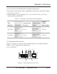
Chapter 2: Overview 2.5.2 LHC202A 1 2 3 4 5 6 7 8 9 Figure 2-3. Front panel of the LHC202A. 10 11 Figure 2-4. Back panel of the LHC202A. 724-746-5500 | blackbox.
Chapter 2: Overview Table 2-3. LHC202A components. Number Component Description 1, 2 (1) dual SC connector (TX/RX) Links to single-mode fiber segment 3, 4, 5, 6, 8, 9 (6) LEDs PWR, LFP, LINK/ACT FX, SPD, FDX/COL, LINK/ACT TP 7 RJ-45 connector Connects to 10/100BASE-TX device 10 (1) barrel connector Links to power 11 (1) 4-position DIP switch TP-Auto or TP-Dis, TP-100M or TP10M, TP FDX or TP-HDX, LFD-ON or LFD-OFF *See Tables 5-1 and 5-2 for LED and DIP switch functions.
Chapter 3: Configuration 3. Configuration To expand a Fast Ethernet network, you can use the converter as described in the following examples: 1. Place two converters back to back between the end devices as shown in Figure 3-1. Device A Twistedpair cable Twistedpair cable Device B 10/100BASE-TX interface LHC201A or LHC202A 100BASE-FX interface LHC201A or LHC202A Single-mode or multimode fiber optic cable Figure 3-1. Application using two media converters.
Chapter 3: Configuration 2. Place one converter directly between a 10/100BASE-TX network segment and a 100BASE-FX network segment as shown in Figure 3-2. Device A 10/100BASE-TX interface Device B 100BASE-FX interface Figure 3-2. Application using one LHC201A or one LHC202A. Page 14 724-746-5500 | blackbox.
Chapter 4: Installation 4. Installation 4.1 Typical Installation 1. The SC fiber connector of an LHC201A transmits/receives data by 1310-nm short-wave laser on multimode fiber. 2. The SC fiber connector of an LHC202A transmits/receives data by 1310-nm short-wave laser on single-mode fiber. Figure 4-1 shows a typical installation. Device A Twistedpair cable Twistedpair cable Device B LHC201A or LHC202A LHC201A or LHC202A Multimode or single-mode fiber optic cable Figure 4-1.
Chapter 4: Installation 2. Connect two converters or a converter and a 100BASE-FX device. • Use an SC fiber cable to connect the two converters’ SC connector or the SC connecter of a converter and a 100BASE-FX device. 3. Turn on the power. Page 16 724-746-5500 | blackbox.
Chapter 5: Operation 5. Operation 5.1 LEDs on the Media Converters The converters have real-time LED indicators that can provide real-time status reports. Just look at the LEDs to determine the link status. Figure 5-1 shows the LEDs and Table 5-1 describes their functions. Figure 5-1. LEDs. 724-746-5500 | blackbox.
Chapter 5: Operation Table 5-1. LED functions. Name PWR Status Description ON Power to the unit is ON. OFF Power to the unit is OFF. ON The Link Fault Passthrough (LFP) function is enabled. OFF The Link Fault Passthrough (LFP) function is disabled. ON There is a valid link. Flashing The converter is receiving or transmitting data from the fiberoptic connector. LFP FX Link/Act OFF There is no valid link. ON The TP port is connected to 100BASE-TX.
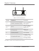
Chapter 5: Operation 5.2 Switch The converters have a 4-position DIP switch. Figure 5-2 shows the DIP switch and Table 5-2 describes its functions. Figure 5-2. DIP switch. 724-746-5500 | blackbox.
Chapter 5: Operation Table 5-2. DIP switch functions. Switch Position Name Position Description TP-AUTO UP The TP port operates in autonegotiation mode. TP-DIS DOWN The TP port operates in FORCE mode. TP-100M UP The TP port operates in 100BASE-TX mode. TP-10M DOWN The TP port operates in 10BASE-T mode. TP_FDX UP The TP port operates in full-duplex mode. TP_HDX DOWN The TP port operates in half-duplex mode. LFP_OFF UP The Link Fault Passthrough function is disabled.
Chapter 5: Operation Table 5-3. Common configurations.
Chapter 5: Operation 5.3 Link Fault Pass Through Function In common situations, when one side of the link fails, the other side continues transmitting packets and waits for a response that never arrives from the disconnected side. With the Link Fault Passthrough function enabled (optional with switch LFP), the TP port and FX port of the same converter will tell each other the fault link status so that when one side of the link fails, the other side will force the link to shut down as soon as noticed.
Chapter 5: Operation Table 5-4. Link LED functions. Link LED Device A OFF Device B OFF FX_LFP FX_Link/Act TP_Link/Act Converter A ON OFF OFF Converter B ON OFF OFF 724-746-5500 | blackbox.
Chapter 6: Troubleshooting 6. Troubleshooting 6.1 Calling Black Box If you determine that your Pure Networking Fast Ethernet Media Converter is malfunctioning, do not attempt to alter or repair the unit. It contains no user-serviceable parts. Contact Black Box Technical Support at 724-746-5500 or info@blackbox.com. Before you do, make a record of the history of the problem.
NOTES 724-746-5500 | blackbox.
NOTES Page 26 724-746-5500 | blackbox.
NOTES 724-746-5500 | blackbox.
Chapter Black Box Tech Support: FREE! Live. 24/7. Tech support the way it should be. Great tech support is just 30 seconds away at 724-746-5500 or blackbox.com. About Black Box Black Box provides an extensive range of networking and infrastructure products. You’ll find everything from cabinets and racks and power and surge protection products to media converters and Ethernet switches all supported by free, live 24/7 Tech support available in 30 seconds or less. © Copyright 2012. Black Box Corporation.