LMC5601C-VDSL2 HDMCII VDSL2 LAN Extender Module (Extended Temp) Use existing phone-grade wiring to support high-bandwidth Ethernet connections.
FCC and IC RFI Statements FCC and Industry Canada RF Interference Statements Class B Digital Device. This equipment has been tested and found to comply with the limits for a Class B computing device pursuant to Part 15 of the FCC Rules. These limits are designed to provide reasonable protection against harmful interference in a residential installation. However, there is no guarantee that interference will not occur in a particular installation.
Certifications Certifications Class 1 Laser product, Luokan 1 Laserlaite, Laser Klasse 1, Appareil A’Laser de Classe European Directive 2002/96/EC (WEEE) requires that any equipment that bears this symbol on product or packaging must not be disposed of with unsorted municipal waste. This symbol indicates that the equipment should be disposed of separately from regular household waste.
Table of Contents Table of Contents Part Numbers ...................................................................................................... 5 1. Specifications ......................................................................................... 6 2. Overview: About the HDMCII VDSL2 LAN Extender Module (Extended Temp).................................................................................... 7 3. Configuration .........................................................................
Part Numbers Part Numbers Part Number LMC5601C-VDSL2 LMC5601C-VDSL2 Description HDMCII VDSL2 LAN Extender Module (Extended Temp) 724-746-5500 | blackbox.
Chapter 1: Specifications 1. Specifications DC Input Operating Temperature Storage Temperature Humidity Dimensions Page 6 662 mA @ 5V -40°F to +185°F (-40°C to +85°C) -67°F to +257°F (-55°C to +125°C) 5% to 95% (non-condensing); 0 to 10,000 ft. altitude Single Slot SNMP Manageable Modules 724-746-5500 | blackbox.
Chapter 2: Overview 2. Overview: About the HDMCII VDSL2 LAN Extender Module (Extended Temp) HDMCII VDSL2 LAN Extender Module (Extended Temp) enables LAN and Campus network managers, and service providers, to use an existing phonegrade wiring to support high bandwidth Ethernet connections. Industry standard 2Base-TL provisions symmetric data delivery over the outside plant defined by IEEE802.3ah.
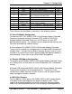
Chapter 3: Configuration 3. Configuration HDMCII VDSL2 LAN Extender Module (Extended Temp) includes various user-configurable features. These features are selectable by using DIP Switches and software. The following sections describe the DIP Switches for the Host CO and Remote CPE module configuration. 3.1 DIP Switch Settings The DIP Switches allow the user to configure most of the module features before installing the unit. These also enable the Host to Remote management channel used with SNMP management.
Chapter 3: Configuration Switch # 1 2 3 Feature HOST LFPT FL 4 Band Plan 5 6 AN Flow Control 7 Selective AN 8 9 10 Duplex Speed Factory Default Function HOST=OFF / Remote=ON On= Link Fault Pass-Through Enabled ON= Fault Loopback Enabled On= Asymmetric 998 with ISDN Off= Symmetric 997 with ISDN On= Auto Negotiation ON On= Flow Control ON On= Selectively advertises Speed Duplex if AN is enabled OFF= Full Duplex / ON= Half Duplex On= 100Mbps / Off= 10Mbps Factory Default: Do not Use Default OFF OFF
Chapter 3: Configuration when Auto Negotiation is not desired by configuring using DIP Switches #8 and #9. 3.5 Auto Negotiation The HDMCII VDSL2 LAN Extender Module (Extended Temp) ships from the factory with Auto Negotiation enabled on the DATA port. In this mode, the DATA port negotiates for speed and duplex (i.e., the module detects 10 Mbps Full-Duplex, 10 Mbps Half-Duplex, 100 Mbps Full-Duplex or 100 Mbps Half-Duplex with Flow Control).
Chapter 3: Configuration Traps can also be set in the iView2 software. A Trap will be generated on any Loss of Signal (LOS); but more importantly, the end user can set a VDSL Quality Level that will generate a trap if the line fails below the assigned level. 3.8 LINK Quality Link Quality is defined by 4 values: 8,4,2,1. The four green LEDs form a binary code indicating the maximum bandwidth the VDSL line can support. The appropriate LED will light once the line quality is dynamically detected.
Chapter 3: Configuration 3.10 Forcing the Data Port Speed The DATA port can be manually configured on HDMCII VDSL2 LAN Extender Module (Extended Temp) for 10 Mbps or 100 Mbps operation. Before manually setting the speed, disable Auto Negotiation (Set DIP Switch #5 to the OFF position.) • • 10 Mbps for the DATA port is configured by setting DIP Switch #9 to the OFF position (default). Configure the DATA port for 100 Mbps operation by setting DIP Switch #9 to the ON position. 3.
Chapter 4: Install the HDMCII VDSL2 LAN Extender Module (Extended Temp) 4. Install the HDMCII VDSL2 LAN Extender Module (Extended Temp) Before installing an HDMCII VDSL2 LAN Extender Module (Extended Temp), set the options using the DIP Switches (refer to the DIP Switch Settings section for more information). Install HDMCII VDSL2 LAN Extender Module (Extended Temp) in any Black Box High-Density Media Converter System II chassis.
Chapter 5: Operation 5. Operation 5.1 LED Operation Each module features diagnostic LEDs that provide information on features and ports. LED RAI FL LOS ER 8-4-2-1 OVF LFPT LOS ER Function VDSL2 The Remote Alarm Indication LED is YELLOW when the unit at the far end of the Unit has an alarm Fault Loopback will be ON GREEN if this function is enabled and BLINK if it is actively inhibiting the Ethernet port due to a LOS of the VDSL line The LOS LED is RED when the VDSL port is down.
Chapter 5: Operation 5.2 Maximum Bandwidth HDMCII VDSL2 LAN Extender Module (Extended Temp) Link LEDs The standard single pair HDMCII VDSL2 LAN Extender Module (Extended Temp) unit will provide the following Rate/Reach performance under the best conditions and still maintain a BER > 10^-9 performance over single pair 24 AWG (0.5mm) twisted wire.
Chapter 5: Operation When the Ethernet port is connected at 10BaseT, the VDSL2 line will be limited to 10 Mbps operation and will indicate a RANGE of 5500 feet or less for all length lines. 5.3 RJ-45 Data Port Pinout (MDI) The following table lists the pin configuration for the RJ-45 Data connector. Pin Signal 1 Transmit+ 2 Transmit3 Receive+ 4 No Connection 5 No Connection 6 Receive7 No Connection 8 No Connection 5.4 RJ-11 Port Pinout VDSL ports are supported on RJ-11 (pin 3,4) connectors.
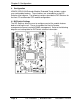
Chapter 5: Operation 5.5 Link Fault Pass-Through FL LNK LNK LNK TX VDSL2 LNK VDSL2 RING LNK FL TIP TIP TX RING LNK LFPT LFPT B RAI RAI When a 10/100BaseT port is lost, the unit sends a fault signal (RAI) to the VDSL line. If the LFPT function is enabled at the Far End VDSL port receiving this fault indication, the far end unit will drop the link on the 10/100BaseT port and BLINK the LFPT LED.
Chapter 6: Troubleshooting 6. Troubleshooting The most common failure of a VDSL line is its slow degradation over time due to aging of the line or increased line noise as additional service is added to the same Line bundle. To help detect this degradation over time, the unit provides a user-defined Minimum Quality Level. Once this level is reached, the unit will send an SNMP TRAP indication for low line quality.
Chapter 7: Contacting Black Box 7. Contacting Black Box Black Box Customer Service Order toll-free in the U.S.: Call 877-877-BBOX (outside U.S. call 724-746-5500) Free technical support, 24 hours a day, 7 days a week. Call: 724-746-5500 or Fax: 724-746-0746 Mail order: Black Box Corporation 1000 Park Drive, Lawrence, PA 15055-1018 Web site: www.blackbox.com E-mail: info@blackbox.com LMC5601C-VDSL2 724-746-5500 | blackbox.
Chapter 8: Fiber Optic Cleaning Guidelines 8. Fiber Optic Cleaning Guidelines Fiber Optic transmitters and receivers are extremely susceptible to contamination by particles of dirt or dust, which can obstruct the optic path and cause performance degradation. Good system performance requires clean optics and connector ferrules. 1.
Chapter 9: Electrostatic Discharge Precautions 9. Electrostatic Discharge Precautions Electrostatic discharge (ESD) can cause damage to any product, add-in modules or stand alone units, containing electronic components. Always observe the following precautions when installing or handling these kinds of products. 1. Do not remove unit from its protective packaging until ready to install. 2. Wear an ESD wrist grounding strap before handling any module or component.
NOTES
NOTES LMC5601C-VDSL2 724-746-5500 | blackbox.
LMC5601C-VDSL2 Rev. 1 51-80970BB-00 Rev.