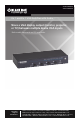
AVSW-VGA4X1A AVSW-VGA8X1A 4 x 1 and 8 x 1 VGA Switches with Audio Share a VGA display output (monitor, projector, BLACK BOX or TV) between multiple device VGA inputs. ® Both models have serial and 3.5-mm audio. Customer Support Information Order toll-free in the U.S.: Call 877-877-BBOX (outside U.S.
FCC and IC RFI Statements and NOM Statement FEDERAL COMMUNICATIONS COMMISSION AND INDUSTRY CANADA RADIO FREQUENCY INTERFERENCE STATEMENTS This equipment generates, uses, and can radiate radio-frequency energy, and if not installed and used properly, that is, in strict accordance with the manufacturer’s instructions, may cause interference to radio communication.
NOM Statement 5. El aparato eléctrico no deberá ser usado cerca del agua—por ejemplo, cerca de la tina de baño, lavabo, sótano mojado o cerca de una alberca, etc. 6. El aparato eléctrico debe ser usado únicamente con carritos o pedestales que sean recomendados por el fabricante. 7. El aparato eléctrico debe ser montado a la pared o al techo sólo como sea recomendado por el fabricante. 8.
NOM Statement 18. Servicio por personal calificado deberá ser provisto cuando: A: El cable de poder o el contacto ha sido dañado; u B: Objectos han caído o líquido ha sido derramado dentro del aparato; o C: El aparato ha sido expuesto a la lluvia; o D: El aparato parece no operar normalmente o muestra un cambio en su desempeño; o E: El aparato ha sido tirado o su cubierta ha sido dañada. Page 4 724-746-5500 | blackbox.
Trademarks Used in this Manual Trademarks Used in this Manual Black Box and the Double Diamond logo are registered trademarks of BB Technologies, Inc. Xbox is a registered trademark of Microsoft Corporation. Wii is a registered trademark of Nintendo of America, Inc. Any other trademarks mentioned in this manual are acknowledged to be the property of the trademark owners. 724-746-5500 | blackbox.
Table of Contents Table of Contents 1. Specifications .............................................................................................. 7 2. Overview .............................................................................................. 8 2.1 Introduction........................................................................................ 8 2.2 Features.............................................................................................. 8 2.3 What’s Included..............
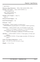
Chapter 1: Specifications 1.
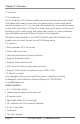
Chapter 2: Overview 2. Overview 2.1 Introduction The 4- and 8-Port VGA Switches enable users to quickly and easily share a single VGA display with several sources from your device inputs to one output device (monitor, projector, or TV). You can select the desired input source via the remote control within the range of 15 feet (5 m) or by using a push button on the switch.
Chapter 2: Overview AVSW-VGA8X1A: • 8 x 1 VGA Video Switch with Audio • Universal power supply with power cord • IR remote control • Serial cable (DB9 F to 2.5-mm plug) • 19" rackmount kit wth mounting hardware • (1) set of foot pads • Screw pack • This user’s manual For both models, you might also need: • Audio cable (EJ110) • 6-ft. (1.8-m) VGA Cable (M-to-M) for VGA A/V source connection (EVNPS06). 2.4 Hardware Description 2.4.
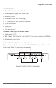
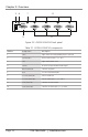
Chapter 2: Overview 5 6 7 8 9 10 Figure 2-2. AVSW-VGA4X1A back panel. Table 2-1. AVSW-VGA4X1A components. Number Component Description 1 LEDs Lights when the corresponding input is selected. 2 Push buttons Press to select input 1, 2, 3, or 4. 3 LED Lights when power is on. 4 Sensor IR sensor accepts remote control signal. 5 Barrel connector Connects to power. 6 DCE 2.5-mm serial control port. 7 3.5-mm connector Links to audio out. 8 3.
Chapter 2: Overview 2.4.2 AVSW-VGA8X1A Front and Back Panels Figure 2-3 shows the front panel of the AVSW-VGA8X1A. Figure 2-4 shows the back panel. Table 2-2 describes its components. 2 5 3 4 1 Figure 2-3. AVSW-VGA8X1A front panel. 6 7 8 11 9 10 12 Figure 2-4. AVSW-VGA8X1 back panel. 724-746-5500 | blackbox.
Chapter 2: Overview Table 2-2. AVSW-VGA8X1A components. Number Component Description 1 LEDs Lights when the corresponding input is selected. 2 Push buttons Press to select input 1, 2, 3, 4. 3 LED Lights when power is on. Press and hold the “S” button, then press the “K1” button to select Port 5. 4 S button Press and hold the “S” button, then press the “K2” button to select Port 6. Press and hold the “S” button, then press the “K3” button to select Port 7.
Chapter 3: Installation 3. Installation Before installation, power off all devices that will be connected to this system. Make sure that all devices you will connect are properly grounded. Place cables away from fluorescent lights, air conditioners, and machines that are likely to generate electrical noise. NOTE: If no screen displays, follow these steps: 1. Make sure the device cables are correctly and firmly attached. 2. Set your display device’s input source as VGA. 3.
Chapter 3: Installation Table 3-1. Connection pattern, AVSW-VGA4X1A. Number Component Description 1 Power supply Apply the proper power to the unit. 2 Video output Connects to the display. 3 Video source (input) Connects to the video source. 4 Serial connector Plug the serial cable in here. 3.2 Installation Steps 1. Use a video cable (VGA) to connect the display to the video output port on the back of the switch. Plug a set of audio jacks from the speaker to the switch’s speaker port. 2.
Chapter 4: Operation (AVSW-VGA4X1A) 4. Operation (AVSW-VGA4X1A) 4.1 Front-Panel Indicators and Push Buttons Figure 4-1. AVSW-VGA4X1A. Table 4-1. Front-panel indicators. Product Code AVSW-VGA4X1A Indicator Description Power LED Lights green when the video switch is powered on. Video Port LEDs 1–4 Lights yellow when the corresponding video port is selected. Table 4-2. Front-panel push buttons.
Chapter 4: Operation (AVSW-VGA4X1A) Figure 4-2. Remote control. 4.3 Serial Control The video switch’s built-in serial interface allows users to control the switch through a PC, serial controller devices, or home theater systems. Configure the controller’s serial port as shown below: Baud Rate: 9600 Data Bits: 8 Parity: None Stop Bits: 1 Flow Control: None Page 16 724-746-5500 | blackbox.
Chapter 4: Operation (AVSW-VGA4X1A) To select a source device via serial interface, select the number that corresponds to the port it is connected to (see Figure 4-3). Figure 4-3. Serial interface screen. NOTE: Use a DB9F-to-2.5-mm cable for the serial connection. 724-746-5500 | blackbox.
Chapter 5: Operation (AVSW-VGA8X1A) 5. Operation (AVSW-VGA8X1A) 5.1 Front-Panel Indicators and Push Buttons To select Source Ports 1–4, simply press the corresponding front-panel button (K1–K4) on the switch. To select Source Port 5, press and hold the “S” button on the switch, then press K1 to select Port 5. To select Source Port 6, press and hold the “S” button on the switch, then press K2 to select Port 6.
Chapter 5: Operation (AVSW-VGA8X1A) Table 5-3. Single-color (yellow) LEDs next to buttons 1–8. LED Number Color Description 1 Yellow The video port on Source 1 is selected. 2 Yellow The video port on Source 2 is selected. 3 Yellow The video port on Source 3 is selected. 4 Yellow The video port on Source 4 is selected. 5 Yellow The video port on Source 5 is selected. 6 Yellow The video port on Source 6 is selected. 7 Yellow The video port on Source 7 is selected.
Chapter 5: Operation (AVSW-VGA8X1A) Figure 5-1. Remote control. Page 20 724-746-5500 | blackbox.
Chapter 6: Troubleshooting 6. Troubleshooting 6.1 Contacting Black Box If you determine that your VGA switch is malfunctioning, do not attempt to alter or repair the unit. It contains no user-serviceable parts. Contact Black Box Technical Support at 724-746-5500 or info@blackbox.com. Before you do, make a record of the history of the problem. We will be able to provide more efficient and accurate assistance if you have a complete description, including: • the nature and duration of the problem.
NOTES Page 22 724-746-5500 | blackbox.
NOTES 724-746-5500 | blackbox.
Black Box Tech Support: FREE! Live. 24/7. Tech support the way it should be. Great tech support is just 30 seconds away at 724-746-5500 or blackbox.com. About Black Box Black Box Network Services is your source for an extensive range of networking and infrastructure products. You’ll find everything from cabinets and racks and power and surge protection products to media converters and Ethernet switches all supported by free, live 24/7 Tech support available in 30 seconds or less. © Copyright 2012.