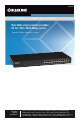
LGB624A 24-Port Web Smart Gigabit Ethernet Switch This Web smart switch provides 24 10-/100-/1000-Mbps ports.BLACK BOX ® Supports Gigabit speed on all ports. Customer Support Information Order toll-free in the U.S.: Call 877-877-BBOX (outside U.S. call 724-746-5500) FREE technical support 24 hours a day, 7 days a week: Call 724-746-5500 or fax 724-746-0746 • Mailing address: Black Box Corporation, 1000 Park Drive, Lawrence, PA 15055-1018 • Web site: www.blackbox.com • E-mail: info@blackbox.
FCC and IC RFI Statements FEDERAL COMMUNICATIONS COMMISSION and INDUSTRY CANADA RADIO FREQUENCY INTERFERENCE STATEMENTS Class B Digital Device. This equipment has been tested and found to comply with the limits for a Class B computing device pursuant to Part 15 of the FCC Rules. These limits are designed to provide reasonable protection against harmful interference in a residential installation. However, there is no guarantee that interference will not occur in a particular installation.
NOM Statement Normas Oficiales Mexicanas (NOM) Electrical Safety Statement INSTRUCCIONES DE SEGURIDAD 1. Todas las instrucciones de seguridad y operación deberán ser leídas antes de que el aparato eléctrico sea operado. 2. Las instrucciones de seguridad y operación deberán ser guardadas para referencia futura. 3. Todas las advertencias en el aparato eléctrico y en sus instrucciones de operación deben ser respetadas. 4. Todas las instrucciones de operación y uso deben ser seguidas. 5.
NOM Statement 12. Precaución debe ser tomada de tal manera que la tierra fisica y la polarización del equipo no sea eliminada. 13. Los cables de la fuente de poder deben ser guiados de tal manera que no sean pisados ni pellizcados por objetos colocados sobre o contra ellos, poniendo particular atención a los contactos y receptáculos donde salen del aparato. 14. El equipo eléctrico debe ser limpiado únicamente de acuerdo a las recomendaciones del fabricante. 15.
Trademarks Used in this Manual Trademarks Used in this Manual Black Box and the Double Diamond logo are registered trademarks of BB Technologies, Inc. Internet Explorer is a registered trademark of Microsoft Corporation. UL is a registered trademark of Underwriters’ Laboratories. Any other trademarks mentioned in this manual are acknowledged to be the property of the trademark owners.
Table of Contents Table of Contents 1. Specifications ................................................................................ 8 2. Overview ................................................................................ 9 2.1 Introduction ................................................................................ 9 2.2 Features ................................................................................ 9 2.3 What’s Included......................................................
Table of Contents s 3.3.3 3.3.4 3.3.5 3.3.6 3.3.7 4. LACP Status.......................................................................... 33 3.3.3.1 LACP Aggregation Overview.................................... 33 3.3.3.2 LACP Port Status...................................................... 34 RSTP Status........................................................................... 34 3.3.4.1 RSTP VLAN Bridge Overview.................................... 34 3.3.4.
Chapter 1: Specifications 1. Specifications Buffer Memory — 500 KB Compliance — FCC Class B; power supply is UL® Listed Filtering/Forwarding Rate — 1000-Mbps port: 1,488,000 pps; 100-Mbps port: 148,800 pps; 10-Mbps port: 14,880 pps Jumbo Frames — 9.6 KB MAC Address — 8K Standards — IEEE 802.3 10BASE-T, IEEE 802.3u 100BASE-TX, IEEE 802.3ab 1000BASE-T, IEEE 802.
Chapter 2: Overview 2. Overview 2.1 Introduction The 24-Port Web Smart Gigabit Ethernet Switch provides 24 10-/100-/1000-Mbps ports. It is designed for easy installation and enables high performance in an environment where traffic on the network and the number of users increases continuously. With the newest Gigabit chipset, this 19" Gigabit Ethernet switch fully supports the highest speed without any problems, even when running full-duplex fully loaded.
Chapter 2: Overview • All ports provide autonegotiation and Auto MDI/MDI-X functions. • S upports flow control: backpressure for half-duplex and IEEE 802.3x for full-duplex mode. • Smart plug and play. 2.3 What’s Included Your package should contain the following items. If anything is missing or damaged, contact Black Box Technical Support at 724-746-5500 or info@blackbox.com. • (1) 24-Port Web Smart Gigabit Ethernet Switch • (1) U.S.
Chapter 2: Overview Table 2-1. 24-Port Web Smart Gigabit Ethernet Switch components. Number Component Description 1 (1) Power LED Lights when power to the unit is on. 2 (24) 1000M LEDs Light when a port is operating at 1000 Mbps. 3 (24) LINK/ACT LEDs Light solid when link is up, blink when data is present, and are off when there is no link. 4 (24) RJ-45 connectors Connect to 10/100/1000 devices. 5 Air vents Maintain proper airflow.
Chapter 3: Software Description 3. Software Description This section explains how to set up and manage the switch through the Web user interface. 3.1 Login First, open the Web browser, and go to 192.168.2.1. The login screen will appear. Type in the password (default password: “admin”) to pass the authentication, and click on the “Apply” button. The following message will appear: “Password successfully entered.” Figure 3-1. Page 12 724-746-5500 | blackbox.
Chapter 3: Software Description 3.2 Configuration 3.2.1 System This page shows system configuration information, as illustrated in Figure 3-3. Figure 3-2. System Configuration screen. LGB624A 724-746-5500 | blackbox.
Chapter 3: Software Description •M AC Address: Displays the unique hardware address assigned by manufacturer (default). • S/W Version: Displays the switch’s firmware version. • H/W Version: Displays the switch’s hardware version. • DHCP Enabled: Click the box to enable DHCP. • F allback IP address: Manually assign the IP address that the network is using. The default IP is 192.168.2.1. • Fallback Subnet Mask: Assign the subnet mask to the IP address.
Chapter 3: Software Description 3.2.2 Ports Port Security ensures access to a switch port based on MAC address, limits the total number of devices from using a switch port, and protects against MAC flooding attacks. 3.2.2.1 Port Configuration In Port Configuration, you can set and view the operation mode for each port. • E nable Jumbo Frames: This switch provides more efficient throughput for large sequential data transfers by supporting jumbo frames on Gigabit Ethernet ports up to 9.6 KB.
Chapter 3: Software Description Figure 3-3. Figure 3-4. Page 16 724-746-5500 | blackbox.
Chapter 3: Software Description 3.2.3 VLAN A Virtual LAN (VLAN) is a logical network grouping that limits the broadcast domain, which would allow you to isolate network traffic, so only the members of the same VLAN will receive traffic from the members of the same VLAN. Basically, creating a VLAN from a switch is logically equivalent to reconnecting a group of network devices to another Layer 2 switch. However, all the network devices are still plugged into the same switch physically. 3.2.3.
Chapter 3: Software Description Figure 3-6. 3.2.3.3 VLAN Per Port Configuration The 802.1Q Per Port Configuration page allows you to change the VLAN parameters for individual ports or trunks. You can configure VLAN behavior for specific interfaces, including the accepted frame types and default VLAN identifier (PVID). Each row of the table corresponds to one port or trunk; trunked ports cannot be configured individually; configure the trunk instead. Figure 3-7. VLAN per port configuration.
Chapter 3: Software Description • Port/Trunk: The port number of the port or the ID of a trunk. •V LAN Aware Enabled: VLAN aware ports are able to use VLAN tagged frames to determine the destination VLAN of a frame. (Default: Enabled) •V LAN aware ports will strip the VLAN tag from received frames and insert the tag in transmitted frames (except for the PVID). VLAN unaware ports will not strip the tag from received frames or insert the tag in transmitted frames.
Chapter 3: Software Description 3.2.4 Aggregation Port trunk allows multiple links to be bundled together and act as a single physical link for increased throughput. It provides load balancing, and redundancy of links in a switched inter-network. Actually, the link does not have an inherent total bandwidth equal to the sum of its component physical links. Traffic in a trunk is distributed across an individual link within the trunk in a deterministic method that called a hash algorithm.
Chapter 3: Software Description •K ey Value: Configures a port's LACP administration key. The port administrative key must be set to the same value for ports that belong to the same link aggregation group (LAG). If this administrative key is not set when an LAG is formed (i.e., it has the null value of 0), this key will automatically be set to the same value as that used by the LAG. Figure 3-9. LACP port configuration screen. 3.2.6 RSTP IEEE 802.
Chapter 3: Software Description • F orward Delay: The maximum time (in seconds) the root device will wait before changing states (i.e., discarding to learning to forwarding). Number between 4–30 (default is 15). • F orce Version: Set and show the RSTP protocol to use. Normal - use RSTP, Compatible—compatible with STP. Figure 3-10. RSTP system configuration. 3.2.6.2 RSTP Port Configuration • Port: The port ID. It cannot be changed. Aggregations mean any configured trunk group.
Chapter 3: Software Description Figure 3-11. RSTP port configuration screen. LGB624A 724-746-5500 | blackbox.
Chapter 3: Software Description Figure 3-12. RSTP system configuration screen. Figure 3-13. RSTP system configuration screen. Page 24 724-746-5500 | blackbox.
Chapter 3: Software Description 3.2.7 IGMP Snooping IGMP Snooping is the process of listening to IGMP network traffic. IGMP Snooping, as implied by the name, is a feature that allows a layer 2 switch to “listen in” on the IGMP conversation between hosts and routers by processing the layer 3 IGMP packets sent in a multicast network. When IGMP Snooping is enabled in a switch, it analyzes all IGMP packets between hosts connected to the switch and multicast routers in the network.
Chapter 3: Software Description 3.2.8 Mirroring Port Mirroring is used on a network switch to send a copy of network packets seen on one switch port (or an entire VLAN) to a network monitoring connection on another switch port. This is commonly used for network appliances that require monitoring of network traffic, such as an intrusion-detection system. 3.2.8.1 Mirroring Configuration • Port to Mirror to: The port that will “duplicate” or “mirror” the traffic on the source port.
Chapter 3: Software Description Figure 3-16. Mirroring configuration screen. 3.2.9 Quality of Service (QoS) In QoS Mode, select QoS Disabled, 802.1p, or DSCP to configure the related parameters. 3.2.9.1 QoS Configuration • S trict: Services the egress queues in sequential order, transmitting all traffic in the higher priority queues before servicing lower priority queues.
Chapter 3: Software Description Figure 3-17. QoS configuration screen. 3.2.9.2 QoS Mode: QoS Disabled When the QoS Mode is set to QoS Disabled, the following table is displayed. Figure 3-18. QoS disabled screen. 3.2.9.3 QoS Mode: 802.1p Packets are prioritized using the 802.1p field in the VLAN tag. This field is three bits long, representing the values 0–7. When the QoS Mode is set to 802.1p, the 802.1p Configuration table appears, allowing you to map each of the eight 802.
Chapter 3: Software Description Figure 3-19. QoS configuration custom selected. Figure 3-20. LGB624A 724-746-5500 | blackbox.
Chapter 3: Software Description 3.2.9.4 QoS Mode: DSCP DSCP: Packets are prioritized using the DSCP (Differentiated Services Code Point) value. The Differentiated Services Code Point (DSCP) is a six-bit field that is contained within an IP (TCP or UDP) header. The six bits allow the DSCP field to take any value in the range 0–63. When QoS Mode is set to DSCP, the DSCP Configuration table is displayed, allowing you to map each of the DSCP values to a hardware output queue (low, normal, medium or high).
Chapter 3: Software Description Figure 3-22. 3.2.10 Storm Control Broadcast storms may occur when a device on your network is malfunctioning, or if application programs are not well designed or properly configured. If there is too much broadcast traffic on your network, performance can be severely degraded or everything can come to complete halt. You can protect your network from broadcast storms by setting a threshold for broadcast traffic for each port.
Chapter 3: Software Description •R ate (number of frames per second): The Rate field is set by a single drop-down list. The same threshold is applied to every port on the switch. When the threshold is exceeded, packets are dropped, irrespective of the flow-control settings. • Web: Click PORTS, Storm Control. This page enables you to set the broadcast storm control parameters for every port on the switch. 3.3 Monitoring 3.3.
Chapter 3: Software Description 3.3.3 LACP Status 3.3.3.1 LACP Aggregation Overview Figure 3-26. • Port: The port number. • Port Active: Shows if the port is a member of an active LACP group. • P artner Port Number: A list of the ports attached at the remote end of this LAG link member. • Operational Port Key: Current operational value of the key used by this LAG. LGB624A 724-746-5500 | blackbox.
Chapter 3: Software Description 3.3.3.2 LACP Port Status Figure 3-27. LACP port status screen. 3.3.4 RSTP Status 3.3.4.1 RSTP VLAN Bridge Overview Figure 3-28. RSTP VLAN bridge overview. • Hello Time: Interval (in seconds) at which the root device transmits a configuration message. • Max Age: The maximum time (in seconds) a device can wait without receiving a configuration message before attempting to reconfigure.
Chapter 3: Software Description • F wd Delay: The maximum time (in seconds) the root device will wait before changing states (i.e., discarding to learning to forwarding). This delay is required because every device must receive information about topology changes before it starts to forward frames. In addition, each port needs time to listen for conflicting information that would make it return to a discarding state; otherwise, temporary data loops might result.
Chapter 3: Software Description • P 2P Port: Shows if this port is functioning as a Point-to-Point connection to exactly one other bridge. The switch can automatically determine if the interface is attached to a point-to-point link or to shared media. If shared media is detected, the switch will assume that it is connected to two or more the switch will assume that it is connected to two or more bridges.
Chapter 3: Software Description •C able Status: Shows the cable length, operating conditions and isolates a variety of common faults that can occur on Category 5 twisted pair cabling. Figure 3-31. Figure 3-32. LGB624A 724-746-5500 | blackbox.
Chapter 3: Software Description Figure 3-33. Figure 3-34. 3.3.7 Ping This command sends ICMP echo request packets to another node on the network. 3.3.7.1 Ping Parameters • Target IP Address: IP address of the host. Page 38 724-746-5500 | blackbox.
Chapter 3: Software Description • Count: Number of packets to send. (Range: 1–20) • Time Out: setting the time period the host will Ping. Use the ping command to see if another site on the network can be reached. The following are some results of the ping command: •N ormal response: The normal response occurs in one to ten seconds, depending on network traffic. •D estination does not respond: If the host does not respond, a “timeout” appears in ten seconds.
Chapter 3: Software Description Figure 3-36. Figure 3-37. Page 40 724-746-5500 | blackbox.
Chapter 4: Maintenance 4. Maintenance 4.1 Warm Restart Press the “Yes” button to restart the switch. The reset will be complete when the power lights stop blinking. Figure 4-1. Warm Reset screen. 4.2 Factory Default This function forces the switch back to the original factory settings. To reset the switch, select “Reset to Factory Defaults” from the drop-down list and click “Apply.” The LAN IP Address, Subnet Mask and Gateway IP Address will be reset to their factory default settings. Figure 4-2.
Chapter 4: Maintenance Figure 4-3. 4.4 Configuration File Transfer Configuration file transfer allows you to save the switch’s current configuration or restore a previously saved configuration back to the device. Configuration files can be saved to any location on the web management station. “Upload” the configuration file to save a configuration or “Download” to restore a configuration. Use the “Browse” button to choose a file location on the Web management station, or to find a saved configuration file.
Chapter 4: Maintenance 4.6 Reset Button for the Factory Default Setting Follow these steps to reset the Web Smart Switch back to the original default: STEP 1: Turn on the Web Smart Switch STEP 2: Press and hold the reset button continuously for 5 seconds and release the reset button. STEP 3: The switch will reboot for 20 seconds and the switch configuration will revert back to the default setting. LGB624A 724-746-5500 | blackbox.
Black Box Tech Support: FREE! Live. 24/7. Tech support the way it should be. Great tech support is just 60 seconds away at 724-746-5500 or blackbox.com. About Black Box Black Box provides an extensive range of networking and infrastructure products. You’ll find everything from cabinets and racks and power and surge protection products to media converters and Ethernet switches all supported by free, live 24/7 Tech support available in 60 seconds or less. © Copyright 2014. Black Box Corporation.