
Technical data


30
CONTROL SOFTWARE FOR SCSI EXTENDER AND SWITCHES
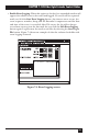
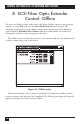
7.2 Online Session Screen Definitions
• Software Title Bar: Defines the name of the software and displays the current
version of the software. For example: “Control Software Version 3.1”.
• Device-Window Title Bar: Defines the current device attached to the serial
port. This information will also provide the ID of the Extender in use. For
example: “Extender #l”. (The numbers at the left are meaningless.)
• Power Indicator: Indicates if the Extender’s power is turned on or off. A yellow
light indicates power is active.
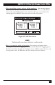
• Link Active Indicator: Indicates if the link between two SCSI Fiber Optic
Extenders is operating properly. A yellow light indicates a proper link between
two Extenders. If the Link Active Indicator is not on, the Extenders will not
operate properly.
• Bus Active Indicator: Indicates when there is SCSI bus activity on the SCSI
Fiber Optic Extenders. When data is transferred across the Extenders, this
indicator will turn on. Typically, this light will flicker as activity moves across
the bus. This is a normal indication of activity.
• Link Error Indicator: Indicates an error between two Extenders. A yellow light
indicates an error in the communication between the two units. When this
light is active, the units will not transfer data properly.
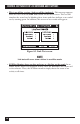
• Fiber Button: When you select this, the yellow light indicates that fiber
communications is selected between two Extenders. This selection will
immediately affect the Extender hardware when clicked. (There is a warning
message before allowing users to change this setting on active units.)
• Coax Button: When selected, the yellow light indicates that the Extenders are
communicating using the coax connection. This button will immediately affect
the Extender hardware when clicked. (There is a warning message before
allowing users to change this setting on active units.)