IC501A SC120A-R2 SC121A SC122A-R2 AUGUST 2002 SC123A SW485A SW487A-R2 SW488A SW489A Control Software for SCSI Fiber Optic Extender, SCSI Matrix Switches, and 6 x 4 Electronic SCSI Switch CUSTOMER SUPPORT INFORMATION Order toll-free in the U.S.: Call 877-877-BBOX (outside U.S. call 724-746-5500) FREE technical support 24 hours a day, 7 days a week: Call 724-746-5500 or fax 724-746-0746 Mailing address: Black Box Corporation, 1000 Park Drive, Lawrence, PA 15055-1018 Web site: www.blackbox.
LICENSE AGREEMENT LICENSE AGREEMENT This manual is shipped with Control Software for your SCSI Switch or Extender. Do not install or use the Software until you have read this License Agreement. By installing or using the Software (or authorizing any person to do so), you accept this License Agreement. If you do not accept this License Agreement, you must return the Software unused. 1. Software.
CONTROL SOFTWARE FOR SCSI EXTENDER AND SWITCHES 8. Disclaimer of Warranties and Limitation on Liability. The manufacturer and its authorized agents disclaim and exclude all implied warranties of noninfringement, merchantability, or fitness for a particular purpose. The manufacturer and its authorized agents do not warrant that this Product will satisfy Licensee’s requirements or that the operation thereof will be uninterrupted.
LEGAL INFORMATION, TRADEMARKS NOTICES AND DISCLAIMERS This manual is copyrighted. All rights are reserved. No part of this manual may be reproduced, transmitted, copied, or translated in any form or by any means, electronic or mechanical, including photocopying and recording, for any purpose without the express written permission of the manufacturer or its authorized agents. The software described in this document is furnished under a license agreement or nondisclosure agreement.
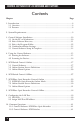
CONTROL SOFTWARE FOR SCSI EXTENDER AND SWITCHES Contents Chapter Page 1. Introduction ............................................................................................................6 1.1 Overview............................................................................................................6 1.2 Features ............................................................................................................6 2. System Requirements..............................................
TABLE OF CONTENTS Chapter Page 11. Error and Warning Messages..............................................................................43 12. Troubleshooting the Extender ..........................................................................49 13. The Extender and Tape Drives ..........................................................................51 13.1 Using SCSI Fiber Optic Extenders with Remote Tape Devices ..............51 13.2 Troubleshooting Extenders Connected to Tape Devices ...........
CONTROL SOFTWARE FOR SCSI EXTENDER AND SWITCHES 1. Introduction 1.
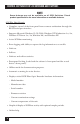
CHAPTER 1: Introduction • Supports Microsoft® Windows® 95/98/2000, Windows NT® Workstation 3.x/4.x, Windows NT Server 3.x/4.x, Windows Me®, and Windows XP®. • Active SCSI-bus monitoring. • “Smart Switching” to avoid a “Y” in the SCSI bus. • “Smart Termination” to avoid termination of active ports. • Supports multiple devices within a single application. • Port naming for documentation purposes. • Front-panel locking (locks the device’s front panel). • Offline mode for demonstration purposes.
CONTROL SOFTWARE FOR SCSI EXTENDER AND SWITCHES NOTE Some features may not be available on all SCSI Switches. Check product specifications for more information on available features. SCSI Fiber Optic Extender • Complete control of the front panel from a remote workstation through the RS-232 serial port interface. • Supports Microsoft Windows 95/98/2000, Windows NT Workstation 3.x/4.x, Windows NT Server 3.x/4.x, Windows Me, and Windows XP. • Active SCSI-bus monitoring.
CHAPTER 2: System Requirements 2. System Requirements BLACK BOX® Control Software requires the following items for proper functionality. • RS-232 Serial Port Connection: The serial connection provides a method of communication between the software running on a workstation or PC to the SCSI Switch or Extender. • Ethernet TCP/IP Connection (SCSI Switches): This option can be used with the SCSI Switches. It allows control of the switches from a remote workstation using TCP/IP for communicating to the switch.
CONTROL SOFTWARE FOR SCSI EXTENDER AND SWITCHES 3. Control Software Installation 3.1 On the PC or Workstation 1. Insert the Control Software CD-ROM into your CD-ROM drive (usually given the drive letter “D”, “E”, or “F”). 2. From the Program Manager, choose File/Run, or from the Start Menu choose Run. 3. If you inserted the CD-ROM in drive D, type D:\setup and choose OK. 4. Follow the installation instructions.
CHAPTER 3: Control Software Installation 3.2 Select Software Directory This directory is where the Control Software will be stored on the local machine. Select the default location and proceed to the next step by clicking Next. without taking any other action. If you want to use some other location, click Browse to locate an alternative directory for the files; once you select your desired location, click Next to continue. Figure 3-1. Choose Destination Location screen.
CONTROL SOFTWARE FOR SCSI EXTENDER AND SWITCHES 3.3 Select the Program Folder The following screen designates where the Control Software will appear under the Start menu. Selecting the default will create a Program Folder called BLACKBOX, with a subfolder called BLACKBOX Control. Click Next to continue. Figure 3-2. Select Program Folder screen.
CHAPTER 3: Control Software Installation 3.4 Confirm Installation Settings The following screen shows the current settings for installing the software based on the selections in the previous screens. If the information is correct, click Next to continue. Figure 3-3. Start Copying Files screen. 3.5 Control Software Setup Is Complete Setup is now complete. Press Finish. Checking Yes, launch the program file will automatically start the Control Software after you select Finish.
CONTROL SOFTWARE FOR SCSI EXTENDER AND SWITCHES Figure 3-4. Setup Complete screen.
CHAPTER 4: Using the Control Software 4. Using the Control Software 4.1 Starting the Software Double-click the Black Box icon to start the software. Figure 4-1. BLACK BOX® Control Software screen.
CONTROL SOFTWARE FOR SCSI EXTENDER AND SWITCHES 4.2 Scanning for Devices Upon initial startup, the software will prompt you with the following message: Figure 4-2. Software prompt upon initial startup. • Auto-detect on-line devices: The software will scan the RS-232 serial port and try to find active devices. This is the normal operation when a hardware device is connected through the RS-232 port. If a device is found, the software will begin operating in an active, online mode.
CHAPTER 5: SCSI Switch Control: Online 5. SCSI Switch Control: Online 5.1 Control Software Once the software detects a device through the RS-232 serial port or Ethernet port, the following screen will appear. If multiple devices are found, each will be represented separately in its own window. In the following example, SC122A-R2 has been identified and is the only unit connected to the PC or workstation.
CONTROL SOFTWARE FOR SCSI EXTENDER AND SWITCHES • Device Product Code: The product code (model number) of the device is shown below the Black Box logo. • Bus Mode: Indicates the mode of operation (interface type) that the SCSI Switch is using: HVD, LVD, or SE. • Smart Switching: This feature is optional and keeps the switch settings from accidentally creating a “Y” on the SCSI bus. This forces each SCSI channel to be isolated.
CHAPTER 5: SCSI Switch Control: Online • Switch Without Holdoff: The SCSI Switches are equipped with a safety feature (Holdoff) that does not allow the changing of the port settings if bus activity is active on the port being changed. There is a delay that can be set up to 25.5 seconds where the bus must be idle for the delay time before settings will become active.
CONTROL SOFTWARE FOR SCSI EXTENDER AND SWITCHES • Show Bus Activity Meters: When selected, a graphical representation of SCSI bus activity will appear directly below the switch information. This meter will rise and fall depending on the amount and consistency of the data being transferred across the SCSI bus on each port. The following is an example with this option selected. Figure 5-3. Online screen with Show Bus Activity Meters selected. 5.
CHAPTER 5: SCSI Switch Control: Online Settings: • Communications: Changes the communication-port settings for proper communication between the PC or workstation and the Switch. The following screen will appear when this option is selected. Figure 5-4. Serial Port and LAN Configuration screen.
CONTROL SOFTWARE FOR SCSI EXTENDER AND SWITCHES Configure [Product Code]: The name of this menu header changes based on the type of device connected and the active window. In each case, the product code of the currently active device will be shown after the word “Configure”—for example, “Configure SC122A-R2.” • Options: This is the only available selection in the “Configure [Product Code]” menu. It provides critical information about the SCSI Switch and allows access to multiple SCSI Switch functions.
CHAPTER 5: SCSI Switch Control: Online 5.4 Configuration Screen Options If you select “Options” under the “Configure [Model Number]” heading in the main online menu, the Configuration screen appears. You can use it to set a number of different options accessible through the screen’s tabs. SCSI Holdoff: These settings define how long the SCSI bus must be idle before allowing any changes to active ports or termination. Figure 5-5. Configuration screen, SCSI Holdoff tab.
CONTROL SOFTWARE FOR SCSI EXTENDER AND SWITCHES Alarm: Provides alarm information for failures and allows the user to set the temperature threshold on the unit. Each indicator when lit represents a failure with the corresponding item. Disabling the audible alarm will turn off the beeping the switch creates when an alarm is triggered. The following is an example of the options available: Figure 5-6. Configuration screen, Alarm tab.
CHAPTER 5: SCSI Switch Control: Online Miscellaneous Configurations: Figure 5-8. Configuration screen, Misc tab. • Lock Front Panel: When checked, the front panel of the switch is locked and will not allow changes to port settings or termination. The software interface, however, will still be able to make any changes. Front-panel locking only affects manual switching. • Set Switch Number: This identifies a specific switch.
CONTROL SOFTWARE FOR SCSI EXTENDER AND SWITCHES Version: Figure 5-9. Configuration screen, Version tab. • Model, Serial Number, and Date of Manufacture are all pulled from the hardware and displayed for informational purposes. • Firmware Version is also pulled from the hardware and is displayed for informational purposes. • LAN Card Detected will be lit as seen in the screen shot if the software successfully detects the switch’s Ethernet LAN card.
CHAPTER 6: SCSI Switch Control: Offline 6. SCSI Switch Control: Offline The offline session is typically used to test the software and become familiar with it before connecting an active device. An offline session can be created either by selecting the Work Offline option as the program starts, or by selecting File and then the New Offline Session menu option. The following screen will appear for selecting which type of hardware device the user wishes to show in offline mode.
CONTROL SOFTWARE FOR SCSI EXTENDER AND SWITCHES The Control Software will create the window for the device selected as shown below for the SCSI Switch. Notice that the device window’s title bar indicates the status is for the Switch, indicating that the device is not actively connected. Figure 6-2. Offline session screen for the SC123A. All the functionality of the software is available for testing in an offline session; however, no actual changes are made to a device.
CHAPTER 7: SCSI Fiber Optic Extender Control: Online 7. SCSI Fiber Optic Extender Control: Online 7.1 SCSI Fiber Optic Extender Online Mode Once the software detects a device through the RS-232 serial port, the following screen will appear. If multiple devices are found, each will be represented separately in its own window. In this example, Extender #1 has been identified and is the only unit connected to the PC or Workstation.
CONTROL SOFTWARE FOR SCSI EXTENDER AND SWITCHES 7.2 Online Session Screen Definitions • Software Title Bar: Defines the name of the software and displays the current version of the software. For example: “Control Software Version 3.1”. • Device-Window Title Bar: Defines the current device attached to the serial port. This information will also provide the ID of the Extender in use. For example: “Extender #l”. (The numbers at the left are meaningless.
CHAPTER 7: SCSI Fiber Optic Extender Control: Online • Self-Test Button: Provides a method for testing the Extender hardware. When clicked, this will immediately start a self-test on the Extender. IMPORTANT A self-test always uses the coax connection for testing. If fiber is used to connect the Extenders, the coax loopback adapter must be installed on the Extender. A self-test will temporarily select the coax connection and turn off the fiber connection to complete the test.
CONTROL SOFTWARE FOR SCSI EXTENDER AND SWITCHES Monitor: • SCSI Bus Monitor...: Displays a graph, similar to this one, of the SCSI-bus activity across the Extenders: Figure 7-5. SCSI Bus Activity Monitor screen. • Sample Period: Provides the interval in seconds for updating the graphical representation of the SCSI bus activity. This timing parameter ranges from 1 ⁄6 of a second to 1 hour. • Reset: Clears the current monitor activity and restarts the monitoring of the SCSI bus.
CHAPTER 7: SCSI Fiber Optic Extender Control: Online In this screen, if “Connect via RS-232 Serial Port” is selected, Port defines which port on the PC or workstation is connected to the RS-232 serial port, while Baud Rate defines the baud rate (in bps) for communicating between the PC or workstation and the Switch. Changes made will immediately affect the communication with the active device. For a description of the Assign IP Address... feature, see Section 9.2.
CONTROL SOFTWARE FOR SCSI EXTENDER AND SWITCHES 7.4 Configuration Screen Options If you select “Options” under the “Configure” heading in the main online menu for the Extender, the Extender’s Configuration screen appears: Figure 7-3. Extender Configuration screen. It will give you information about the Extender and you can use it to set a few configuration options. • Model, Serial Number, and Date of Manufacture are all pulled from the hardware and displayed for informational purposes.
CHAPTER 7: SCSI Fiber Optic Extender Control: Online • Enable Error Logging: When this option is checked, an expanded window will appear that allows errors to be noted and logged. No errors will be captured until you click the Start Error Logging button. Any time an error occurs, the error sequence number, along with the Extender’s temperature and the date and time of the error, is recorded.
CONTROL SOFTWARE FOR SCSI EXTENDER AND SWITCHES 8. SCSI Fiber Optic Extender Control: Offline To create an offline session, either select the Work Off-line option as the program initiates, or select File and then the New Off-line Session menu option. The following screen represents an offline session. Note the title bar in the Extender control window. Extender #96 indicates no Extenders are connected through the software control program at this time.
CHAPTER 8: SCSI Fiber Optic Extender Control: Offline • This is an off-line session—self test will be simulated... This message appears when you click the Self-Test button on the main screen. The test will simulate the actual test by blinking three times and then indicate a successful test by turning green. In addition, this screen of test results will appear: Figure 8-2. Self-Test screen. NOTE Self-tests will never show a failure in an offline mode. • Sorry—you must be on-line to log errors.
CONTROL SOFTWARE FOR SCSI EXTENDER AND SWITCHES • This is an off-line session—link test will be simulated... This message appears when the user clicks the Link Test button on the main screen. The test will simulate the actual test by blinking three times and then indicate a successful test by turning green. In addition, this screen of test results will appear: Figure 8-3. Link Test screen. NOTE Link tests will never show a failure in an offline mode.
CHAPTER 9: Configuring the LAN Port 9. Configuring the LAN Port 9.1 LAN Port The SCSI Switch may be controlled over a TCP/IP network through its LAN port. You can remotely control the SCSI Switch via a standard 10-Mbps Ethernet connection running TCP/IP. In the SCSI Switches’ factory-default setting, the LAN port will be enabled and the RS-232 COM2 port (which uses the same circuitry and is used for daisychaining SCSI Switches) will be disabled.
CONTROL SOFTWARE FOR SCSI EXTENDER AND SWITCHES Figure 9-2. Configure Network Switch screen. Apconcfg Utility The apconcfg.exe utility is used to configure the TCP/IP address. Enter the new IP address and switch MAC address in the appropriate fields. The MAC address can be found on a label located on the bottom of the SCSI Switch. Search for Black Box Network Switches You can search for the IP address by clicking the Search button in the Configure Network Switch.
CHAPTER 10: Common Questions 10. Common Questions 10.1 Control Software: SCSI Fiber Optic Extender Q.How do I lock the front panel so others don’t change the settings? A. Select the Configuration option from the main menu and check the Lock Front Panel box. Click OK and the panel will be locked. This also locks the software front panel as well as the unit front panel. Q. How do I activate the software error logging? A.
CONTROL SOFTWARE FOR SCSI EXTENDER AND SWITCHES Q. Why can I still select ports through the front panel that create a “Y” on the SCSI bus when “Smart Switching” is selected in the software? A. “Smart Switching” options are only for use with the Control Software interface and do not affect the front-panel operation. Locking the front panel will keep users from changing switch settings manually. Q. Why is the switch showing a bus mode of SE when I have an LVD controller? A.
CHAPTER 11: Error and Warning Messages 11. Error and Warning Messages Most errors and warnings generated by the Control Software apply only to the SCSI Fiber Optic Extender. Those that also apply to the SCSI Switches are marked “Switches and Extender:”. Sorry—you must be on-line to log errors. This message only appears when using an offline session with SCSI Fiber Optic Extenders.
CONTROL SOFTWARE FOR SCSI EXTENDER AND SWITCHES Switches and Extender: No devices were detected Error 10101. This message appears after scanning for online devices. Common reasons for the message: • The hardware is not connected to the RS-232 serial port. • The hardware is turned off. • Communication-port settings are not correct. • Make sure the comm port and baud rate are properly defined. • Serial cable unplugged from the PC or BLACK BOX hardware. • Bad serial cable.
CHAPTER 11: Error and Warning Messages Error Limit Reached (254). Click on the Start Error Logging button to reset the error counter. This message appears when monitoring Extender bus activity and the number of errors across the bus have exceeded 254. It appears within the error log window. NOTE Each error might not appear in the error log window. If a burst of errors happens extremely rapidly, the log will not be able to capture and display the error information.
CONTROL SOFTWARE FOR SCSI EXTENDER AND SWITCHES Link Test FAILED. This message appears at the top of the Link Test Statistics window on the Extender after a Link Test has been unsuccessfully performed. Common reasons for the message: • The Link Test is performed when the Link Active light is not on, indicating that the units are not properly communicating. This following message box will appear if a Link Test is initiated while the Link Active light is off: Figure 11-2. Link not active screen.
CHAPTER 11: Error and Warning Messages Self Test FAILED. This message appears at the top of the Self Test Statistics window on the Extenders after a self-test has been unsuccessfully performed. Common reasons for the message: • The loopback DB9 coax adapter is not plugged into the DB9 coax port on the back of the Extender. This is required when fiber is used as the communication between two Extenders for the self-test to properly operate.
CONTROL SOFTWARE FOR SCSI EXTENDER AND SWITCHES Self Test will temporarily switch from FIBER to COAX. Since the link is currently active, this may cause your system to crash. The Self Test uses the Coax interface for testing the unit. This requires the unit to switch from the Fiber interface while the test is completing. This message only appears if Fiber is the selected interface and the Link Active light is lit.
CHAPTER 12: Troubleshooting the Extender 12. Troubleshooting the Extender Issue: Self-Test is failing. Resolution: • Make sure the DB9 loopback adapter shipped with the Extender is connected if you’re using fiber to connect the two units. If this device is not connected, the self-test will always fail. • If you’re using coax to connect the two Extenders, make sure you have not exceeded the length specifications of the coax cable. Issue: Link Test is failing.
CONTROL SOFTWARE FOR SCSI EXTENDER AND SWITCHES Issue: Front panel does not remain locked. Resolution: • The front panel will not maintain a locked status if the power has been cycled on the Extender. This setting is only active as long as power is maintained on the units. To permanently lock the front panel even after a power cycle, use the rear DIP switches on the Extender.
CHAPTER 13: The Extender and Tape Drives 13. The Extender and Tape Drives 13.1 Using SCSI Fiber Optic Extenders with Remote Tape Drives The performance of tape drives used with Extenders will vary depending on the configuration. There are five known variables that significantly change the performance of the SCSI bus when using tape drives with the Extender. 1. Isolation of the Bus—The first Extender should be connected directly to the host adapter isolating the bus for the remote devices.
CONTROL SOFTWARE FOR SCSI EXTENDER AND SWITCHES 13.2 Troubleshooting Extenders Connected to Tape Devices Issue: Tape devices not targeting or SCSI bus locks up while in operation. Resolution(s): • Make sure the Link Test on the Extenders runs without errors by pressing Link Test on the front panel. If it fails, then the fiber connection between the two units is not working properly. This is normally an issue with the fiber cable connection or excessive fiber or coax length.
CHAPTER 13: The Extender and Tape Drives • Are other devices, such as drives or other peripherals, on the same SCSI bus? If so, try moving the tape drives with the Extenders to a separate SCSI bus managed by their own host adapter. • Is the tape drive being driven from an on-board SCSI host adapter? Move the drive with the Extenders to a separate board within the system. This will ensure that the drives are isolated on their own bus.
CONTROL SOFTWARE FOR SCSI EXTENDER AND SWITCHES 14. SCSI Installation Tips Keep your SCSI chain short. Official SCSI specifications limit a SCSI single-ended chain to no more that 6 meters (19.7 feet) long. Practical experience says the shorter, the better. The maximum length you should allow between devices is 3 feet. Never assign the same SCSI ID number to two devices on the same bus. SCSI uses these numbers as addresses to ensure that information goes to the correct location.
CHAPTER 15: Uninstalling the Control Software 15. Uninstalling the Control Software Take these steps regardless of which version of Windows you’re running: 1. Open the Control Panel and double-click the Add/Remove Programs icon. 2. Select Black Box Control and click the Add/Remove button. 3. Click Yes to confirm the removal of the program when prompted. 4. Software will be removed from the system. NOTE Uninstall removes all of the installed files and registry settings.
CONTROL SOFTWARE FOR SCSI EXTENDER AND SWITCHES 16. Calling Technical Support 16.1 Calling Black Box If you determine that your Control Software, SCSI Switch, or SCSI Extender is malfunctioning, do not attempt to alter or repair it. It is not user-serviceable. Contact Black Box at 724-746-5500. Before you do, make a record of the history of the problem.
© Copyright 2002. Black Box Corporation. All rights reserved.