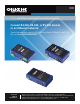
LES401A LES402A LES404A 1-, 2-, and 4-Port Industrial Ethernet Serial Servers Connect RS-232, RS-422, or RS-485 devices BLACK BOX to an Ethernet network. ® Access the serial ports over a LAN/WAN using Direct IP Mode, Virtual COM Port, or Paired Mode connections. Customer Support Information Order toll-free in the U.S.: Call 877-877-BBOX (outside U.S.
Trademarks Used in this Manual Trademarks Used in this Manual Black Box and the Double Diamond logo are registered trademarks of BB Technologies, Inc. VT100 is a trademark of Digital Equipment Corporation. HyperTerminal is a registered trademark of Hilgraeve, Inc. Internet Explorer, Microsoft, Windows, and Windows Vista are registered trademarks of Microsoft Corporation. Any other trademarks mentioned in this manual are acknowledged to be the property of the trademark owners.
FCC and NOM Statement Federal Communications Commission and Industry Canada Radio Frequency Interference Statements This equipment generates, uses, and can radiate radio-frequency energy, and if not installed and used properly, that is, in strict accordance with the manufacturer’s instructions, may cause interference to radio communication.
NOM Statement Instrucciones de Seguridad (Normas Oficiales Mexicanas Electrical Safety Statement) 1. Todas las instrucciones de seguridad y operación deberán ser leídas antes de que el aparato eléctrico sea operado. 2. Las instrucciones de seguridad y operación deberán ser guardadas para referencia futura. 3. Todas las advertencias en el aparato eléctrico y en sus instrucciones de operación deben ser respetadas. 4. Todas las instrucciones de operación y uso deben ser seguidas. 5.
Table of Contents Table of Contents Serial Server Quick Start Guide.............................................................................................................................................. 7 1. Specifications ........................................................................................................................................................... 10 1.1 General..............................................................................................................
Table of Contents 5.4 5.5 Search for Servers........................................................................................................................................... 30 Configure Server Properties............................................................................................................................ 31 6. Configuring the Serial Server Properties.....................................................................................................................
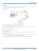
Quick Start Guide Quick Start Guide For descriptive purposes, this Quick Start Guide considers a typical configuration consisting of a PC connected via an Ethernet LAN to a 2-Port Industrial Serial Server connected to the RS-232 port of a serial device. Hardware Setup Figure QS-1. Typical hardware setup. Step 1: Connect the Serial Server to the network using a standard network cable. Step 2: Connect the Serial Server to the RS-232 port on the serial device.
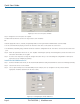
Quick Start Guide Figure QS-2. The Server Properties window. Step 3: Change the Server Properties as required. • Enable DHCP to allow the Serial Server to generate its own IP address OR • Obtain appropriate static IP, netmask, and gateway addresses from your Network Administrator (recommended). • Set the Serial Port Mode property to RS-232 to match the serial device connected to the Serial Server.
Quick Start Guide Check Communications Step 1: From the Windows Start menu, run HyperTerminal. Step 2: Configure HyperTerminal to connect using the COM port configured in the last section (for example, Port 15). Step 3: Set Baud Rate, Data/Parity/Stop, and Flow Control to match the configuration of the serial device connected to the Serial Server serial port. Step 4: Communications with the serial device should now be operational. 724-746-5500 | blackbox.
Chapter 1: Specifications 1. Specifications 1.1 General Approvals — FCC, IP30 case Configuration Options — Console mode: Using RS-232 with VT100™ emulation; Telnet mode: Using HyperTerminal with VT100 emulation; Serial Server Manager: Windows® 98/ME/2000/2003 Server/XP, Windows NT, Windows Vista®; Web server: Using Internet Explorer® Web browser Data Rate — 110 bps to 230.
Chapter 1: Specifications Power Requirements — 8 VAC to 24 VAC or 9 VDC to 48 VDC Power consumption: LES401A: 320 mA @ 12 VDC, LES402A: 340 mA @ 12VDC, LES404A: 360 mA @ 12 VDC; Power supply start-up time: ≤24 ms Power connector: Terminal block Size — 1.75"H x 6.1"W x 4.1"D (4.46 x 15.52 x 10.46 cm) 1.
Chapter 1: Specifications Figure 1-1. 1-Port Serial Server dimensions. Figure 1-2. 2-Port Serial Server dimensions. Figure 1-3. 4-Port Serial Server dimensions. Page 12 724-746-5500 | blackbox.
Chapter 2: Overview 2. Overview 2.1 Introduction 1-, 2-, and 4-Port Port Industrial Ethernet Serial Servers enable connection of RS-232, RS-422, or RS-485 devices to an Ethernet network. You can access the serial ports over a LAN/WAN using Direct IP Mode, Virtual COM Port, or Paired Mode connections. The 10-/100-Mbps Ethernet connection auto-selects 10BASE-T or 100BASE-TX and indicates the type of connection with a bi-color link light.
Chapter 2: Overview Figure 2-1. 1-, 2-, and 4-Port Industrial Serial Servers. 2.2 Features •M ulti-interface serial ports: The 1-Port Industrial Serial Server features one multi-interface serial port and the choice of standard DB9 M or removable terminal block connections (switch selectable). The 2-Port Industrial Serial Server features two multi-interface serial ports. The 4-Port Industrial Serial Server features four multi-interface serial ports.
Chapter 2: Overview • UDP mode allows broadcast to and from multiple IP addresses. • Management access password protected. • Configure the Ethernet and serial port settings using any of four methods: 1. Serial Server Manager Software for Windows enables configuration via a network connection or directly from the Ethernet port of a computer (using an Ethernet crossover cable). 2. Web Server enables configuration via the network using a Web browser. 3.
Chapter 2: Overview 2.3.3 Paired Mode Paired Mode is also called serial tunneling. In this mode, any two serial devices that can communicate with a serial link will be able to communicate using two Serial Servers and the LAN. Two Serial Servers are connected to a network, one configured as a TCP or UDP client and the other as a TCP/UDP server. When setting up the server the remote IP address section must contain the address of the client.
Chapter 2: Overview Table 2-1. 1-Port Serial Server components. Number Component Description 1 (1) terminal block connector Used for DC power. 2 (1) Link LED Lights yellow for 10BASE-T or green for 100BASE-TX. 3 (1) Ready LED Flashes green when the unit is ready to transmit/receive data. 4 (1) Power LED Lights when power to the unit is on. 5 (1) Reset button Press to reset the unit. 6 (1) 2-position DIP switch Selects run or console mode.
Chapter 2: Overview Table 2-2 (Continued). 2-Port Serial Server components. Number Component Description 6 (1) 2-position DIP switch Selects run or console mode. 7 (1) RJ-45 Ethernet connector Connects to Ethernet. 8 (2) RX LEDs Light when data is being received at the serial ports. 9 (2) TX LEDs Light when data is being transmitted from the serial ports. 10 (2) DB9 connectors Connect to serial devices. 1 2 3 4 5 6 7 8 9 10 8 9 10 9 8 9 10 8 10 Figure 2-4. 4-Port Serial Server.
Chapter 3: Hardware Configuration 3. Hardware Configuration 3.1 Serial Server Indicators, Switches, and Connectors 3.1.1 Indicators • One bi-color Link LED (Yellow = 10BASE-T, Green = 100BASE-T) • One green Ready LED (flashing = system ready) • One red Power LED • One red RX LED and one green TX LED for each serial port 3.1.2 Switches Reset A recessed reset switch that enables the unit to be reset. Insert a small plastic tool, press lightly and hold for three seconds.
Chapter 3: Hardware Configuration Power Connector The power connector is a removable terminal block with four terminals. From top to bottom the terminals are: Table 3-1. Power connector. Terminal GND AC in Connect to Description Negative side of DC power supply (if DC power used). Also connect negative side of backup DC power supply (if used).
Chapter 3: Hardware Configuration 3.2.4 RS-232 Mode In RS-232 Mode, the currently selected serial port is configured as an RS-232 interface supporting eight RS-232 signal lines plus Signal Ground and is configured as a DTE, like a computer. Signals are single-ended and referenced to Ground. To use handshaking, Flow Control must be set to RTS/CTS during configuration. 3.2.
Chapter 3: Hardware Configuration Table 3-2. 1-Port Industrial Serial Server bias jumpers. Connector Interface Type 485 half-duplex Terminal block 422/485 full-duplex 485 half-duplex DB9 422/485 full-duplex CTS Jumper Number Pull Up/Pull Down J12 Pull up J6 Pull down J7 Pull up J13 Pull down J3 Pull up J9 Pull down J5 Pull up J11 Pull down J4 Pull up J10 Pull down Figure 3-2. 2-Port Industrial Serial Server bias jumper locations. Table 3-3.
Chapter 3: Hardware Configuration Figure 3-3. 4-Port Industrual Serial Server. Table 3-4. 4-Port Industrial Serial Server bias jumpers.
Chapter 4: Installing the Software 4. Installing the Software The Windows based Serial Server Manager and Virtual COM Port software makes configuration fast and easy. If using Windows, we recommend installing the Serial Server Manager software and setting up virtual COM ports to configure the Serial Server. The Serial Server software includes: • Serial Server Manager software • Install Virtual COM Ports • Uninstall Virtual COM Ports 4.
Chapter 4: Installing the Software Figure 4-4. The Choose Destination window. Step 3: When Choose Destination Location appears, click “Next.” The installation progress will be shown until complete. Figure 4-5. The Install Shield Wizard Complete window. Step 4: Click “Finish” when the Install Shield Wizard Complete dialog appears. When finished, the dialog box will close. 724-746-5500 | blackbox.
Chapter 4: Installing the Software 4.3 Updating an Existing Installation If an older version of the Serial Server Manager software is already installed, the “Modify, Repair, or Remove the Program” window will appear when the installation process is initiated: Figure 4-6. The InstallShield Wizard Modify, Repair, or Remove the Program window. We recommend removing all installed components first. Once the software has been removed, Install the new software. 4.
Chapter 5: Using Serial Server Manager 5. Using Serial Server Manager The Serial Server Manager software enables: • Searching for servers connected to the network. • Displaying and changing the configuration of those servers. • Installing virtual COM ports on a computer. • Displaying and configuring virtual COM ports. • Uninstalling virtual COM ports on a computer. • Upgrading the serial server firmware. • Monitoring port status. • Saving and loading configuration files. 5.
Chapter 5: Using Serial Server Manager NOTE: If connecting directly to a computer LAN card, use an Ethernet Crossover Cable (as in Figure 5-2). Figure 5-2. Direct Ethernet connection using a crossover cable. Step 2: Apply power. The red Power indicator will light. The Link indicator lights when an Ethernet connection is made, and the Ready indicator will flash. 5.2 Software Setup Step 3.
Chapter 5: Using Serial Server Manager 5.3 Software Overview The Serial Server Manager window provides the following information: • Menus (Server, View, Exit, Help) • Server Icons (Firmware Upgrade, Virtual COM Configuration, Searching Server, Uninstall Virtual COM, Monitor Port Status) • Serial Server/Virtual COM Lists • Software Status (Ready, Updating, Searching, etc.) 5.3.1 Menus Server • Firmware Upgrade—Used when downloading new firmware to the Serial Server.
Chapter 5: Using Serial Server Manager 5.3.2 Server Icons Pane Firmware Upgrade, Virtual COM Configuration, Searching Server, Uninstall Virtual COM, and Monitor Port Status can also be selected using icons located in the left window. 5.3.3 Serial Server/Virtual COM Lists To make managing lists of serial servers easier, lists can be sorted by clicking on any tab heading. Scrolling bars help when scrolling through long lists. Serial Server List • Server Name—Displays the name of the Serial Server.
Chapter 5: Using Serial Server Manager Step 5: Enter the IP Address assigned to the desired Serial Server or click “Search all reachable servers,” then click “OK.” IP Address is used to find Serial Server units that are not on the same subnet. (Routers on the network will block the standard broadcast used to find servers if Search all reachable servers is selected.) The user must set an IP address that conforms to the LAN addressing scheme.
Chapter 6: Configuring the Serial Server Properties 6. Configuring the Serial Server Properties The Serial Server can be configured using any of four different user interfaces: the Serial Server Manager software, Console Mode, Telnet, or the Web Server. The Server Properties described in this chapter can be changed from any of these user interfaces. Figure 6-1. The four methods of configuring server properties. Figure 6-2. Serial Server Manager Server Properties window. Page 32 724-746-5500 | blackbox.
Chapter 6: Configuring the Serial Server Properties Server Name This field displays the name that has been assigned to the Serial Server. You can enter a new Server Name of up to 16 characters. If more than one Serial Server is connected on the LAN, we recommend that you assign a new name to each. When the Serial Server Manager finds a Serial Server on the LAN, it displays the server name and IP Address, enabling the user to distinguish between Serial Servers.
Chapter 6: Configuring the Serial Server Properties Figure 6-3. Pinging using the DOS command window. Netmask The default LAN netmask is configured for a Class C address. The user may change this. The default is 255.255.255.0. Gateway The gateway IP address allows users to access the Serial Server from outside the LAN. MAC Address The MAC address is fixed and cannot be changed. It is assigned in the factory. Every Ethernet device manufactured has it own unique MAC address.
Chapter 6: Configuring the Serial Server Properties UDP Mode When UDP mode is chosen, the Serial timeout, TCP alive timeout, Connection mode, Connection at, Max connection, and Remote IP address fields are replaced with the following fields: Destination IP address range, Port number, and Source IP address range. In this mode, you can configure the server to broadcast data to and receive data from multiple IP addresses. Four IP address range fields are provided. Figure 6-4.
Chapter 6: Configuring the Serial Server Properties Force Transmit This field allows the user to set a maximum time limit between transmissions of data. The value set in this field multiplied by 100 ms determines the Force Transmit time. When the elapsed time reaches the time configured in this field, the TCP/IP protocol will pack the data currently in the serial buffer into a packet and send it out the Ethernet port.
Chapter 6: Configuring the Serial Server Properties If Paired Mode is not being used, do not change this setting until the application has been tested and is communicating properly. Then activate the address filtering feature. NOTE: Refer to Section 2.3.3, Paired Mode. Update/Save Server properties must be updated separately for each serial port. Updating varies slightly, depending on which of the four configuration user interfaces are used.
Chapter 7: Installing Virtual COM Ports 7. Installiing Virtual COM Ports The Virtual COM Port feature allows Windows platform software, using standard API calls, to be used in an Ethernet application. The Install Virtual COM Port software adds a Serial Server (COM#) port to the computer. This shows up in the Device Manager. The COM number can be selected from a list of available numbers. For example, in a computer already having a COM 1 and COM 2, COM 3 to COM 254 are available for the Serial Server.
Chapter 7: Installing Virtual COM Ports Figure 7-3. The COMInst window. Step 4: In the Map To: field, select the number of the virtual COM port to be assigned. The default Flow Control setting is None. RTS/CTS can be selected if used by the application program and serial hardware. The Serial Server must be set to match. The protocol TCP/UDP, IP address, and port number will mirror the settings of the selected serial server. Click “OK.
Chapter 7: Installing Virtual COM Ports 7.2 Matching the Serial Server and Virtual COM Port Settings The settings of the virtual COM ports in the Device Manager and the Serial Server Configuration Menu must match. If the settings do not match, the virtual COM ports will not work. If these settings are changed in the Device Manager, it will only affect the operation of the virtual COM port. It will not change the settings stored in the Serial Server.
Chapter 7: Installing Virtual COM Ports Figure 7-6. The Serial Server (COM3) Properties window. Step 4: Click the “Configuration” or “Port Settings” tab. This screen allows the settings to be changed if necessary. Click “Cancel” to keep the existing settings. Step 5: Click “OK” to change the settings. Use Refresh in the Device Manager if Windows does not auto refresh. 724-746-5500 | blackbox.
Chapter 8: Removing Virtual COM Ports 8. Removing Virtual COM Ports 8.1 Using Serial Server Manager Step 1: From the Windows Desktop, click: “Start —> Programs —> Serial Server” Step 2: In the Serial Server Manager window, click the Virtual COM List tab. Highlight the mapped COM port number to be removed. Figure 8-1. The Serial Server Manager window. Step 3: Click the “Uninstall Virtual COM” icon. The Manager will ask for conformation. Click “OK” to complete the uninstall procedure. 8.
Chapter 8: Removing Virtual COM Ports Figure 8-2. The Control Panel window. Step 3: Click “Device Manager” in the Systems Properties window. In the Device Manager dialog box, click the “+” next to Ports (COM LPT) to expand. Figure 8-3. The Device Manager window. Step 4: Highlight Serial Server (COM#) to be removed and click the “Action” tab at the top of window, then click “Uninstall.” A Confirm Device Removal window will appear. 724-746-5500 | blackbox.
Chapter 8: Removing Virtual COM Ports Figure 8-4. Confirm Device Removal. Step 5: Click “OK” to proceed. The Serial Server (COM#) will be removed and the Device Manager window will refresh and display the remaining COM ports. Page 44 724-746-5500 | blackbox.
Chapter 9: Upgrading the Serial Server Firmware 9. Upgrading the Serial Server Firmware New Serial Server firmware updates may become available through the Black Box Web site (www.blackbox.com) for installation into the server. The firmware can be uploaded using either a virtual COM port connection or hardware COM port connection. 9.1 Downloading the Firmware Make a folder to receive the firmware file. Download the compressed software file from www.blackbox.com. Unzip or expand the file into the (.
Chapter 9: Upgrading the Serial Server Firmware Figure 9-1. The Port Settings window. Step 10: Upgrade progress will be shown until the Upgrade finished! message is shown. Click “OK.” Page 46 724-746-5500 | blackbox.
Chapter 10: Using Console Mode 10. Using Console Mode Before the Serial Server is installed on a LAN, the Console Mode can be used to change the settings from the defaults. The Serial Server is shipped in the RS-232 Mode. Connect a crossover (null-modem) cable between the COM port on the computer and the appropriate serial port on the Serial Server. NOTE: See Chapter 6 for details of each server property settings. Console Mode Setup Step 1: Apply power to the Serial Server.
Chapter 10: Using Console Mode Figure 10-1. Console Mode Configuration screens. Page 48 724-746-5500 | blackbox.
Chapter 10: Using Console Mode Step 6: Once all the changes have been made, move to the Configuration screen, select “Save” and press “Enter.” Figure 10-2. Saving and restarting the configuration. The restart message will appear. Step 7: Select “Yes” to save changes. This is necessary to write the settings to the server. Using a Password If a password is used, you must enter it before the Configuration screen will appear.
Chapter 11: Using the Web Server 11. Using the Web Server The Web Server can be used to configure the Serial Server from any Web browser software (such as Internet Explorer). Server properties can be set up using three browser pages. NOTE: See Chapter 6 for details on server properties. Setting Server Properties In Internet Explorer, type the IP address of the Serial Server into the address field near the top of the window and press the Enter key. The following window will appear: Figure 11-1.
Chapter 11: Using the Web Server To change serial port properties, click “Serial Port” on the left side of the browser window. The following page will appear: Figure 11-2. The Web Server Serial Port Properties page. To change other operational properties, click “Operation” on the left side of the browser window. The following page will appear: 724-746-5500 | blackbox.
Chapter 11: Using the Web Server Figure 11-3. The Web Server Operation page. Click “Save” to store changes to the Serial Server. Settings for each port must be saved separately. NOTE: If new property settings are not saved before leaving this page, they will not take effect. Return to the main Server page by clicking on “Server” on the left side of the browser window. Page 52 724-746-5500 | blackbox.
Chapter 12: Using Telnet 12. Using Telnet You can use Telnet to configure the Serial Server from any PC on the LAN. The Telnet window displays the same configuration information shown in Console Mode and allows server properties to be configured. NOTE: See Chapter 6 for details on Server Properties. Configuration Using Telnet Step 1: Make sure that the PC and Serial Server are connected to the LAN. Step 2: Apply power to the Serial Server. The power and ready LED will light.
Chapter 12: Using Telnet Figure 12-2. Telnet Configuration screens. Step 7: Once all the changes have been made, move to the Save field and select “Enter.” The restart message will appear. Figure 12-3. Saving and Restarting the Configuration Step 8: Select “Yes” to save changes. This is necessary to write the settings to the server. The Telnet window will disappear. Step 9: To view the changes, re-enter Telnet and re-establish communications.
Appendix A: RS-232 Connections Appendix A. RS-232 Connections A.1 2- and 4-Port Serial Server DB9 Pinouts in RS-232 Mode Figure A-1. DB9 connector. Table A-1. DB9 connector pinout. RS-232 Signal Name DTE RS-232 DB9 M Pin Carrier Detect In DCD 1 Receive Data In RXD 2 Transmit Data Out TXD 3 Data Terminal Ready Out DTR 4 Signal Ground — GND 5 Data Set Ready In DSR 6 Request To Send Out RTS 7 Clear To Send In CTS 8 Ring Indicator In RI 9 A.
Appendix B: RS-422/485 Connections Appendix B. RS-422/485 Connections B.1 2- and 4-Port Serial Server DB9 Pinout in RS-422 Mode Figure B-1. DB9 connector. Table B-1. RS-422 connections in a DB9 connector.
Appendix B: RS-422/485 Connections B.2 1-Port Serial Server Terminal Block Pinout in RS-422 Mode Figure B-2. Terminal block connector. Table B-2. 1-Port serial terminal block pinout in RS-422 mode. Signal Name RS-422 RS-232 Terminal Signal Ground — GND 1 Transmit Data (-) TXD(-) Out 2 Transmit Data (+) TXD(+) Out 3 Receive Data (+) RXD(+) In 4 Receive Data (-) RXD(-) In 5 In the RS-422 mode, TXD lines are outputs and RXD lines are inputs.
Appendix C: RS-485 Connections Appendix C. RS-485 Connections C.1 1-, 2-, or 4-Port Serial Server DB9 Pinout in RS-485H (Two-Wire, Half-Duplex) Mode Figure C-1. DB9 male connector. Table C-1. DB9 pinout in RS-485H mode. RS-485 Signal Name Direction RS-485 DB9 M Pin Data B (+) In/Out DATA B (+) 3 Data A (-) In/Out DATA A (-) 4 Signal Ground — GND 5 C.2 1-, 2-, or 4-Port Serial Server DB9 Pinout in RS-485F (Four-Wire, Full-Duplex) Mode Figure C-2. DB9 male connector. Table C-2.
Appendix C: RS-485 Connections C.3 1-Port Serial Server Terminal Block Pin-out in RS-485F (Four-Wire, Full-Duplex) Mode Figure C-3. Terminal block connector. Table C-3. Terminal block connector pinning in RS-485F mode. Signal Name RS-422 Direction Terminal Signal Ground GND — 1 Transmit Data (-) TXD(-) Out 2 Transmit Data (+) TXD(+) Out 3 Receive Data (+) RXD(+) In 4 Receive Data (-) RXD(-) In 5 724-746-5500 | blackbox.
Appendix D: Network Connections Appendix D. Network Connections D.1 Standard Ethernet Cable RJ-45 Pinout Figure D-1. RJ-45 connector. Table D-1. T-568A straight-through Ethernet cable connector pinout. RJ-45 Pin Signal Wire Color RJ-45 Pin 1 TX+ White-Green 1 2 TX- Green 2 3 RX+ White-Orange 3 4 Not used Blue 4 5 Not used White-Blue 5 6 RX- Orange 6 7 Not used White-Brown 7 8 Not used Brown 8 Table D-2. T-568B straight-through Ethernet cable connector pinout.
Appendix D: Network Connections D.2 Crossover Ethernet Cable RJ-45 Pinout Figure D-2. RJ-45 connector. Table D-3. RJ-45 Ethernet crossover cable connector pinout. RJ-45 Pin Signal Wire Color RJ-45 Pin 1 TX+ White-Green 3 2 TX- Green 6 3 RX+ White-Orange 1 4 Not used Blue 4 5 Not used White-Blue 5 6 RX- Orange 2 7 Not used White-Brown 7 8 Not used Brown 8 724-746-5500 | blackbox.
NOTES Page 62 724-746-5500 | blackbox.
NOTES 724-746-5500 | blackbox.
Black Box Tech Support: FREE! Live. 24/7. Tech support the way it should be. Great tech support is just 30 seconds away at 724-746-5500 or blackbox.com. About Black Box Black Box provides an extensive range of networking and infrastructure products. You’ll find everything from cabinets and racks and power and surge protection products to media converters and Ethernet switches all supported by free, live 24/7 Tech support available in 30 seconds or less. © Copyright 2012. Black Box Corporation.