
User manual
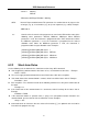
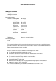

Table Of Contents
- 1.1 Feature Overview
- 1.2 Input Power and Fuse Requirements
- 1.3 Package Contents
- 2.1 Front Panel Overview
- 2.2 Screen Display
- 2.3 Front Panel Menu Options
- 2.4 Front Panel Menu Overview
- Rear Panel Summary
- 2.6 Power up
- 3.1 Overview
- 3.2 Measuring Voltage
- 3.3 Measuring Current
- 3.4 Measuring Resistance
- 3.5 Measuring Frequency and Period
- 3.6 Measuring Continuity
- 3.7 Testing Diode
- 3.8 Math Functions
- 4.1 Measurement configuration
- 4.2 Trigger Operations
- 4.3 Buffer Operations
- 4.4 Limit Operations
- 4.5 System Operations
- 5.1 Selecting an Interface
- 5.2 USB & RS-232 Interface Operation
- 5.3 GPIB Interface operation (model 5492BGPIB only)
- 5.4 Data Format
- 6.1 Command Structure
- 6.2 Command Syntax
- 6.3 Command Reference
- 7.1 Frequently Asked Questions
- 7.2 Error Messages
- 8.1 Technical Specifications
SCPI Command Reference
62
Chapter 6 SCPI Command Reference
This chapter is outlined as follows:
6.1 Command Structure
6.2 Command Syntax
6.3 Command Reference
6.1 Command Structure
The remote commands are divided into two types: Common commands and SCPI commands. The
common commands are defined in IEEE std. 488.2-1987, and these commands are common for all
devices. Not all commands are supported by the 5492B, and some commands are not supported by the
GPIB interface for the 5492BGPIB. Please look through the command syntax thoroughly before
programming. The SCPI commands are used to control most of the 5492B functions. They can be
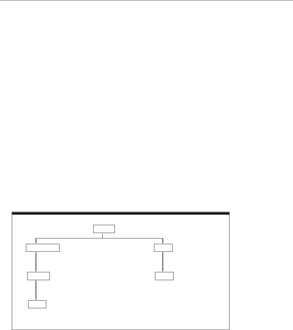
represented as a tree structured with three levels deep. (The highest level commands are called the
subsystem commands in this manual.) The lower level commands are part of subsystem commands and
a colon (:) is used to separate the higher level commands and the lower level commands. See Figure 6-1
as an example.
SENSe
RESistance HOLD
RANGe STATe
SENS:RES:RANG 1k SENS:HOLD:STAT ON
AUTO
SENS:RES:RANG:AUTO ON
Figure 6-1 Command Tree Example