
User manual
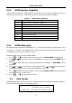
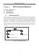
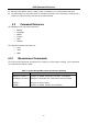
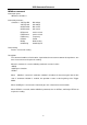
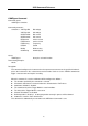

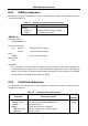
Table Of Contents
- 1.1 Feature Overview
- 1.2 Input Power and Fuse Requirements
- 1.3 Package Contents
- 2.1 Front Panel Overview
- 2.2 Screen Display
- 2.3 Front Panel Menu Options
- 2.4 Front Panel Menu Overview
- Rear Panel Summary
- 2.6 Power up
- 3.1 Overview
- 3.2 Measuring Voltage
- 3.3 Measuring Current
- 3.4 Measuring Resistance
- 3.5 Measuring Frequency and Period
- 3.6 Measuring Continuity
- 3.7 Testing Diode
- 3.8 Math Functions
- 4.1 Measurement configuration
- 4.2 Trigger Operations
- 4.3 Buffer Operations
- 4.4 Limit Operations
- 4.5 System Operations
- 5.1 Selecting an Interface
- 5.2 USB & RS-232 Interface Operation
- 5.3 GPIB Interface operation (model 5492BGPIB only)
- 5.4 Data Format
- 6.1 Command Structure
- 6.2 Command Syntax
- 6.3 Command Reference
- 7.1 Frequently Asked Questions
- 7.2 Error Messages
- 8.1 Technical Specifications
Remote Operation
61
5.3.2 GPIB Interface Capability
Table 5-3 lists the multimeter’s GPIB capabilities and functions. These functions provide the mean for an
instrument to receive, process, and transmit commands, data, and status over the GPIB bus.
Table 5-3 GPIB interface Capability
Code Function
SH1 Complete Source Handshake capability
AH1 Complete Acceptor Handshake capability
T5 Basic Talker; Talk-Only; Unaddressed if MLA; no serial poll.
L4 Basic Listener; Unaddressed if MTA; no Listen Only.
RL1 Remote/Local capability
DC1 Device Clear capability
DT1 Device Trigger capability
C0 No controller capability
E1 Drivers are open-collector
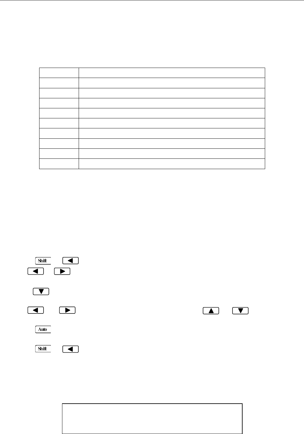
5.3.3 GPIB Addressing
The factory default setting for the GPIB address is 8. You can set the address to a value of 0 to 31 and
the address is saved in the non-volatile memory. Do not assign the same address to another device or
a controller that are on the same GPIB bus system.
Follow the below steps to change the GPIB address:
1. Press → to enter the menu on the menu level, “A: MEAS MENU” will be displayed.
2. Use or key to move across the I/O MENU on the menu level, “E: I/O MENU” will be
displayed.
3. Press to move down to the command level within the I/O MENU, “1: GPIB ADDR” will be
displayed.
4. Use and keys to choose a numerical place and use and keys to increment
or decrement the digits. Enter a value for the GPIB address (0 to 31).
5. Press (ENTER) to confirm the address. The message “CHANGE SAVED” will be displayed to
show that the change is now in effect.
6. Press → key to exit from the menu.
5.4 Data Format
5492BGPIB outputs the measurement results using the ASCII character string format via the GPIB bus.
The data format is described in the following Figure 5-5.
SD.DDDDDDESDDD<NL>
S: +/- E: exponent sign (“+”is omitted)
D: number 0 to 9 <NL>: New Line; Termination character
Figure 5-5 Data Format