
User manual
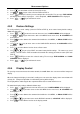
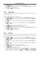
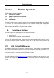
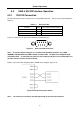
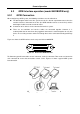
Table Of Contents
- 1.1 Feature Overview
- 1.2 Input Power and Fuse Requirements
- 1.3 Package Contents
- 2.1 Front Panel Overview
- 2.2 Screen Display
- 2.3 Front Panel Menu Options
- 2.4 Front Panel Menu Overview
- Rear Panel Summary
- 2.6 Power up
- 3.1 Overview
- 3.2 Measuring Voltage
- 3.3 Measuring Current
- 3.4 Measuring Resistance
- 3.5 Measuring Frequency and Period
- 3.6 Measuring Continuity
- 3.7 Testing Diode
- 3.8 Math Functions
- 4.1 Measurement configuration
- 4.2 Trigger Operations
- 4.3 Buffer Operations
- 4.4 Limit Operations
- 4.5 System Operations
- 5.1 Selecting an Interface
- 5.2 USB & RS-232 Interface Operation
- 5.3 GPIB Interface operation (model 5492BGPIB only)
- 5.4 Data Format
- 6.1 Command Structure
- 6.2 Command Syntax
- 6.3 Command Reference
- 7.1 Frequently Asked Questions
- 7.2 Error Messages
- 8.1 Technical Specifications
Remote Operation
60
5.3 GPIB Interface operation (model 5492BGPIB only)
5.3.1 GPIB Connection
When configuring a GPIB system, the following restrictions must be adhered to.
The total length of cable in one bus system must be less than or equal to two meters times the
number of devices connected on the bus (the GPIB controller counts as one device) and the
total length of cable must not exceed 20 meters.
A maximum of 15 devices can be connected on one bus system.
There are no restrictions on how the cables are connected together. However, it is
recommended that no more than four piggyback connectors be stacked together on any one
device. The resulting structure could exert enough force on the connector mounting to damage
it.
Figure 5-3 shows the GPIB interface on the rear panel of the 5492BGPIB.
Figure 5-3 Rear Panel GPIB Interface
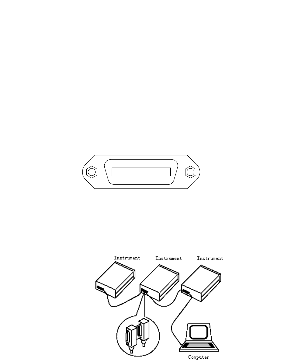
To allow many parallel connections to one instrument, stack the connector. Two screws are located on
each connector to ensure that connections remain secure. Figure 5-4 shows a typical GPIB system
interconnection.
Figure 5-4 Typical GPIB System Interconnection