
User manual
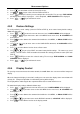
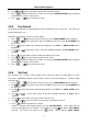
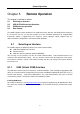
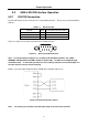
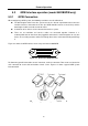
Table Of Contents
- 1.1 Feature Overview
- 1.2 Input Power and Fuse Requirements
- 1.3 Package Contents
- 2.1 Front Panel Overview
- 2.2 Screen Display
- 2.3 Front Panel Menu Options
- 2.4 Front Panel Menu Overview
- Rear Panel Summary
- 2.6 Power up
- 3.1 Overview
- 3.2 Measuring Voltage
- 3.3 Measuring Current
- 3.4 Measuring Resistance
- 3.5 Measuring Frequency and Period
- 3.6 Measuring Continuity
- 3.7 Testing Diode
- 3.8 Math Functions
- 4.1 Measurement configuration
- 4.2 Trigger Operations
- 4.3 Buffer Operations
- 4.4 Limit Operations
- 4.5 System Operations
- 5.1 Selecting an Interface
- 5.2 USB & RS-232 Interface Operation
- 5.3 GPIB Interface operation (model 5492BGPIB only)
- 5.4 Data Format
- 6.1 Command Structure
- 6.2 Command Syntax
- 6.3 Command Reference
- 7.1 Frequently Asked Questions
- 7.2 Error Messages
- 8.1 Technical Specifications
Remote Operation
56
5.2 USB & RS-232 Interface Operation
5.2.1 RS-232 Connection
The RS-232 interface on this instrument uses a 9-pin DB9 connector. The pin outs are defined below in
Table 5-1:
Table 5-1 RS-232 Pin Out
Function Code 9 Pin Connector Pin Number
Transmitted Data TXD 3
Received Data RXD 2
Signal Ground Common GND 5
Figure 5-1 shows the rear panel connector for the RS232 interface.
Figure 5-1 Rear Panel RS232 Interface
Note: To interface with a serial port on a computer with the RS232 interface, use a NULL
MODEM or CROSS OVER serial DB-9 female to female cable. Do NOT use a straight-through
serial DB-9 cable. To check that you have the correct cable, probe pin 2 on one end and pin 3 on
the other and vice versa to check continuity.
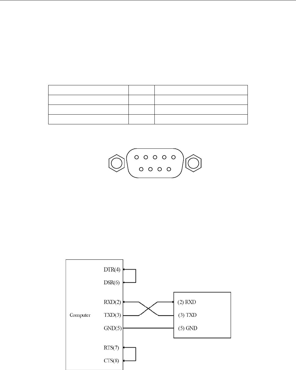
Below is a pin connection diagram between 5492B and a computer (Figure 5-2):
Figure 5-2 RS-232 Connection Sketch
Note: Pin 4 and 6, pin 7 and 8 are shorted respectively at the end of the controller.