
User manual
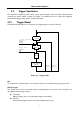
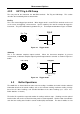
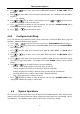
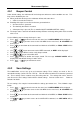
Table Of Contents
- 1.1 Feature Overview
- 1.2 Input Power and Fuse Requirements
- 1.3 Package Contents
- 2.1 Front Panel Overview
- 2.2 Screen Display
- 2.3 Front Panel Menu Options
- 2.4 Front Panel Menu Overview
- Rear Panel Summary
- 2.6 Power up
- 3.1 Overview
- 3.2 Measuring Voltage
- 3.3 Measuring Current
- 3.4 Measuring Resistance
- 3.5 Measuring Frequency and Period
- 3.6 Measuring Continuity
- 3.7 Testing Diode
- 3.8 Math Functions
- 4.1 Measurement configuration
- 4.2 Trigger Operations
- 4.3 Buffer Operations
- 4.4 Limit Operations
- 4.5 System Operations
- 5.1 Selecting an Interface
- 5.2 USB & RS-232 Interface Operation
- 5.3 GPIB Interface operation (model 5492BGPIB only)
- 5.4 Data Format
- 6.1 Command Structure
- 6.2 Command Syntax
- 6.3 Command Reference
- 7.1 Frequently Asked Questions
- 7.2 Error Messages
- 8.1 Technical Specifications
Measurement Options
47
4.3.3 Buffer Statistics
In addition to measured readings that can be stored into the internal buffer, four other statistical
information of the stored readings are also kept inside the buffer. They are: MAX, MIN, AVG, STD.
MAX and MIN
The MAX and MIN refer to the maximum and minimum value of the readings stored in the buffer
respectively.
For example, suppose the buffer contains the following five readings: 1.234, 2.345, 3.456, 4.567, 5.678.
MAX = 5.678
MIN = 1.234
AVR
AVR stands for average. The AVR value is the mean(average) of the buffered readings. The equation
used to calculate this is:
=
Where:
is a stored reading
is the number of stored readings
For example, suppose the buffer contains the following five readings: 1.234, 2.345, 3.456, 4.567, 5.678.
AVG = 3.456
STD
The STD value is the standard deviation of the buffered readings. The equation used to calculate the
standard deviation is:
=
1
1
Where:
is a stored reading
is the number of stored readings
4.4 Limit Operations
Limit operations set and control the values that determine the HI / IN / LO status of subsequent
measurements. Limits can be applied to all measurement functions except continuity. The limit test is
performed after mX+b and percent math operations. Unit prefixes are applied before the limit test, for
example:
Low Limit = -1.0, High Limit = 1.0
A 150mV reading becomes 0.15V (IN).
Low Limit = -1.0, High Limit = 1.0