
User manual
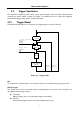
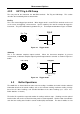
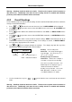
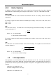
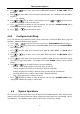
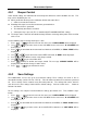
Table Of Contents
- 1.1 Feature Overview
- 1.2 Input Power and Fuse Requirements
- 1.3 Package Contents
- 2.1 Front Panel Overview
- 2.2 Screen Display
- 2.3 Front Panel Menu Options
- 2.4 Front Panel Menu Overview
- Rear Panel Summary
- 2.6 Power up
- 3.1 Overview
- 3.2 Measuring Voltage
- 3.3 Measuring Current
- 3.4 Measuring Resistance
- 3.5 Measuring Frequency and Period
- 3.6 Measuring Continuity
- 3.7 Testing Diode
- 3.8 Math Functions
- 4.1 Measurement configuration
- 4.2 Trigger Operations
- 4.3 Buffer Operations
- 4.4 Limit Operations
- 4.5 System Operations
- 5.1 Selecting an Interface
- 5.2 USB & RS-232 Interface Operation
- 5.3 GPIB Interface operation (model 5492BGPIB only)
- 5.4 Data Format
- 6.1 Command Structure
- 6.2 Command Syntax
- 6.3 Command Reference
- 7.1 Frequently Asked Questions
- 7.2 Error Messages
- 8.1 Technical Specifications
Measurement Options
44
4.2.2 EXT Trig & VM Comp
The rear panel of the instrument has two BNC terminals: Ext Trig and VM Comp. This section
describes the functionality of these two terminals.
Ext Trig
This is the external trigger input terminal. When trigger mode is set to EXT, this terminal can be used
as the source for triggering a measurement. Input a negative pulse into this terminal to trigger the
instrument. The pulse width must be greater than 1 μs. An example is illustrated in Figure 4-3 below.
5 V
0 V
Iutput
Ext Trig
>
1μs
Figure 4-3 Trigger model
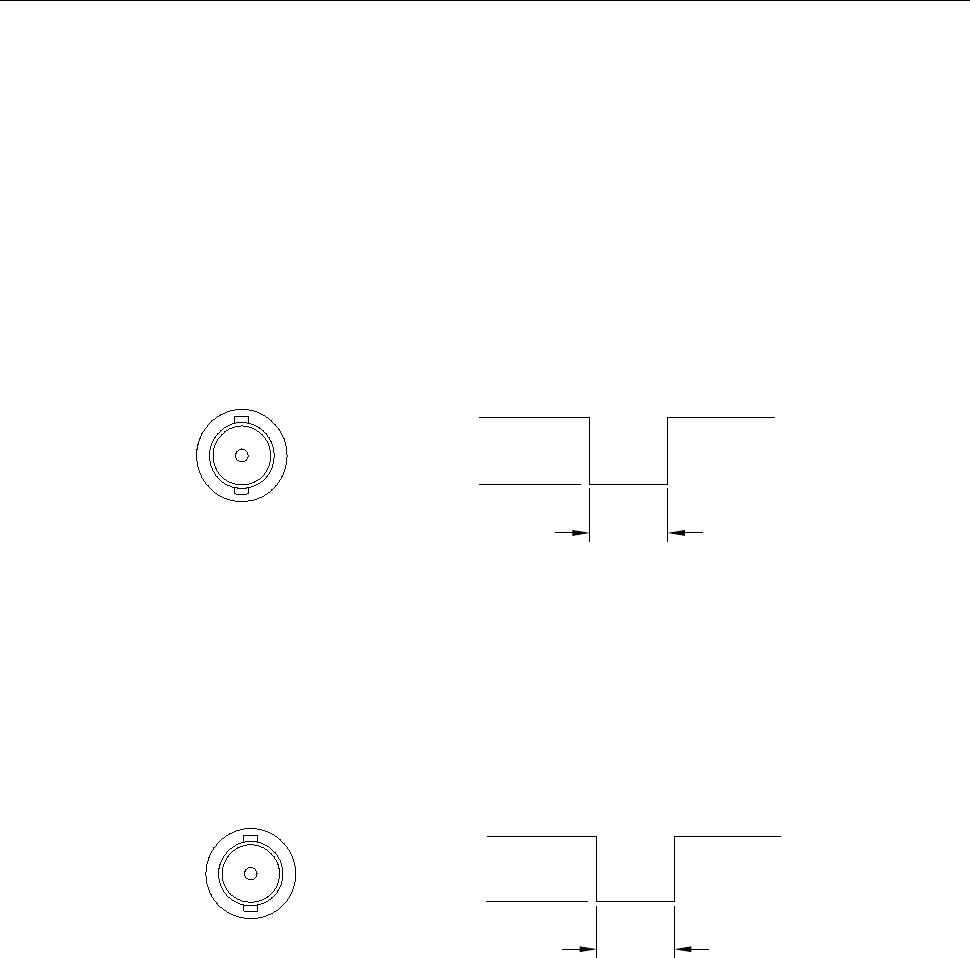
VM Comp
This is the voltmeter complete output terminal. When the instrument completes its present
measurement, a voltmeter complete output signal will output from this terminal as shown in Figure 4-4
below.
5 V
0 V
Output
VM Comp
Approximately
2
μ
s
Figure 4-4 Trigger model
4.3 Buffer Operations
The 5492B has an internal buffer to store 2 to 512 readings. In addition, the buffer includes statistical
information based on the stored readings such as the minimum reading, maximum reading, average
based on the stored readings, and standard deviation of the stored readings
(See section “4.3.3
Buffer Statistics” for details).
The buffer fills up with the requested number of readings and then stops. Readings are then placed
into the buffer and can be read back via front panel or remote operation. Buffered data is overwritten
each time the reading store function is turned enabled (ON) and initiated. The data is volatile; it is not
Input