
User manual
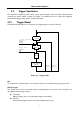
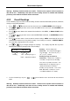
Table Of Contents
- 1.1 Feature Overview
- 1.2 Input Power and Fuse Requirements
- 1.3 Package Contents
- 2.1 Front Panel Overview
- 2.2 Screen Display
- 2.3 Front Panel Menu Options
- 2.4 Front Panel Menu Overview
- Rear Panel Summary
- 2.6 Power up
- 3.1 Overview
- 3.2 Measuring Voltage
- 3.3 Measuring Current
- 3.4 Measuring Resistance
- 3.5 Measuring Frequency and Period
- 3.6 Measuring Continuity
- 3.7 Testing Diode
- 3.8 Math Functions
- 4.1 Measurement configuration
- 4.2 Trigger Operations
- 4.3 Buffer Operations
- 4.4 Limit Operations
- 4.5 System Operations
- 5.1 Selecting an Interface
- 5.2 USB & RS-232 Interface Operation
- 5.3 GPIB Interface operation (model 5492BGPIB only)
- 5.4 Data Format
- 6.1 Command Structure
- 6.2 Command Syntax
- 6.3 Command Reference
- 7.1 Frequently Asked Questions
- 7.2 Error Messages
- 8.1 Technical Specifications
Measurement Options
41
4.2 Trigger Operations
The multimeter’s triggering system allows you to generate triggers either manually, automatically, or
externally for taking multiple readings per trigger. The following discusses front panel triggering,
programmable trigger delay, and the reading hold feature.
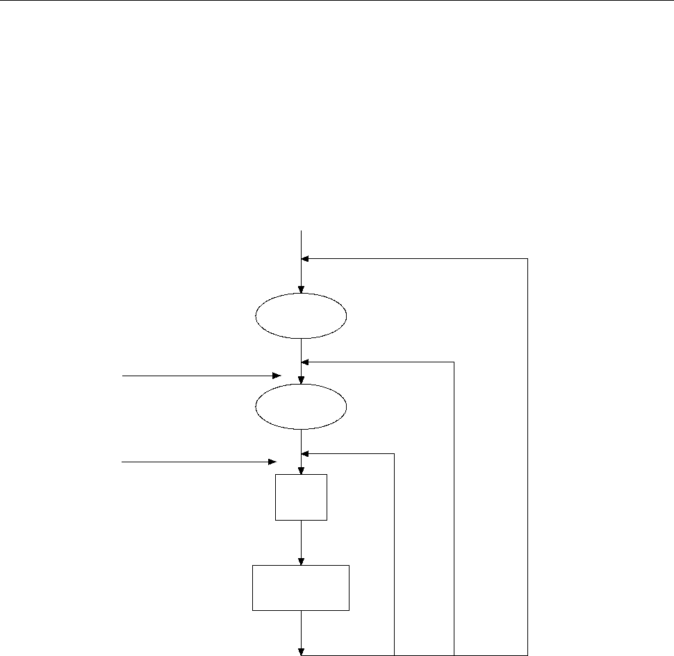
4.2.1 Trigger Model
The flowchart below (Figure 4-2) summarizes the triggering process of the instrument.
count
≠
1
Trigger
1
≠
count
sample
MAN
BUS
IMMediate
Trigger source
Initiate Triggering
INITiate
READ?
MEASure?
sample
Measurement
Delay
Wait for
Trigger
Idle
state
Figure 4-2 Trigger model
Idle
The instrument is considered to be in the idle state whenever it is not performing any measurement.
Wait for Trigger
The control source holds up operation until the programmable event occurs and is detected. See
description below for trigger sources:
Immediate
With this trigger source, event detection happens immediately.
External
Event detection happens when either of the following takes place: