
User manual
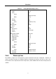
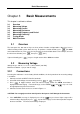
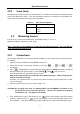
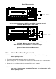
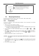
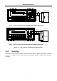
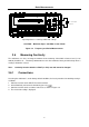
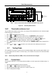
Table Of Contents
- 1.1 Feature Overview
- 1.2 Input Power and Fuse Requirements
- 1.3 Package Contents
- 2.1 Front Panel Overview
- 2.2 Screen Display
- 2.3 Front Panel Menu Options
- 2.4 Front Panel Menu Overview
- Rear Panel Summary
- 2.6 Power up
- 3.1 Overview
- 3.2 Measuring Voltage
- 3.3 Measuring Current
- 3.4 Measuring Resistance
- 3.5 Measuring Frequency and Period
- 3.6 Measuring Continuity
- 3.7 Testing Diode
- 3.8 Math Functions
- 4.1 Measurement configuration
- 4.2 Trigger Operations
- 4.3 Buffer Operations
- 4.4 Limit Operations
- 4.5 System Operations
- 5.1 Selecting an Interface
- 5.2 USB & RS-232 Interface Operation
- 5.3 GPIB Interface operation (model 5492BGPIB only)
- 5.4 Data Format
- 6.1 Command Structure
- 6.2 Command Syntax
- 6.3 Command Reference
- 7.1 Frequently Asked Questions
- 7.2 Error Messages
- 8.1 Technical Specifications
Basic Measurements
28
3.5 Measuring Frequency and Period
Frequency measurement range: 5 Hz to 1 MHz.
Period measurement range: 0.2 s to 1 μs.
Input signal range: 120 mV AC to 750 V AC RMS.
The instrument uses the volts input terminals (INPUT HI and INPUT LO) to measure frequency and
period. The AC voltage range can be changed with the RANGE and keys. However, the
signal voltage must be greater than 10% of the full-scale range.
Note: Auto ranging is not available for frequency and period measurement function.
3.5.1 Trigger Level and Measurement Errors
Frequency and Period apply a zero-crossing trigger, meaning that a count is taken when the signal
crosses the zero level.
The multimeter uses an interactive counting technique to measure frequency and period. This method
generates constant measurement resolution for any input frequency. All frequency counters are
subject to errors when measuring low voltage, low frequency signals. Both internal noise and external
noise are also critical when measuring low voltage, low frequency signals. Measurement errors will
also occur if you attempt to measure the frequency (or period) of an input following a dc offset voltage
change. You must allow the multimeter’s DC input blocking capacitor to fully settle before making
frequency measurements.
3.5.2 Gate Time
Gate time is the amount of time the multimeter uses to sample frequency or period readings. For model
5492B, all RATE settings (Fast, Med and Slow) yield a gate time of one second.
3.5.3 Connections
Assuming the multimeter is under factory default conditions, the basic procedure for measuring
frequency or period is as follows:
1. Connect test leads to INPUT HI and LO terminals.
2. Select frequency or period measurement functions by pressing or →
respectively.
3. Connect test leads to the source as shown in Figure 3-4:
CAUTION: Do not exceed 1000 V peak between INPUT HI and INPUT LO or instrument damage
may occur.
4. The measured reading is displayed.