
User manual
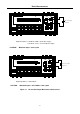
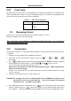
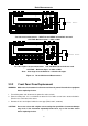
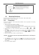
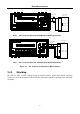
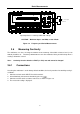
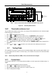
Table Of Contents
- 1.1 Feature Overview
- 1.2 Input Power and Fuse Requirements
- 1.3 Package Contents
- 2.1 Front Panel Overview
- 2.2 Screen Display
- 2.3 Front Panel Menu Options
- 2.4 Front Panel Menu Overview
- Rear Panel Summary
- 2.6 Power up
- 3.1 Overview
- 3.2 Measuring Voltage
- 3.3 Measuring Current
- 3.4 Measuring Resistance
- 3.5 Measuring Frequency and Period
- 3.6 Measuring Continuity
- 3.7 Testing Diode
- 3.8 Math Functions
- 4.1 Measurement configuration
- 4.2 Trigger Operations
- 4.3 Buffer Operations
- 4.4 Limit Operations
- 4.5 System Operations
- 5.1 Selecting an Interface
- 5.2 USB & RS-232 Interface Operation
- 5.3 GPIB Interface operation (model 5492BGPIB only)
- 5.4 Data Format
- 6.1 Command Structure
- 6.2 Command Syntax
- 6.3 Command Reference
- 7.1 Frequently Asked Questions
- 7.2 Error Messages
- 8.1 Technical Specifications
Basic Measurements
27
Shielded
Coble
Optional
Shield
Resistance
Under Test
▲
▲
▲
▲
DC V AC V 2W Fr eq
Aut o
Tr i
g
MX + B
Shi f t
Cont Re l
¦¸
Period
dB/m
FastMenu Recall Med Slow Hold
CHOICES
LEVEL ENTER
ESC
LOCAL
%
IDC IAC 4W
Ω
FAST
MED
SLOW
ADRS RMT HOLD TRIG
*
MEM AUTO
REL FILT MATH SHIFT
4W
ERR
POWER
T2AL 250V
SENSE
Ω4W
V
Ω
LO
HI
!
10A
CATⅡ(300V)
CATⅠ(1000V)
350V
MAX
1000V
MAX
12A
MAX
mA
12A
INPUT
R
5
5492B
1
2
/
Digit Multimeter
Note: Source current flows from the INPUT HI to INPUT LO terminals
T2AL 250V
SENSE
Ω
4W
V
Ω
LO
HI
!
10A
CATⅡ(300V)
CATⅠ(1000V)
350V
MAX
1000V
MAX
12A
MAX
mA
12A
INPUT
Shielded
Coble
Optional
Shield
Resistance
Under Test
▲
▲
▲
▲
DC V AC V 2W Fr eq
Aut o
Tr i
g
MX + B
Shi f t
Co n t Rel
¦¸
Period
dB/m
FastMenu Recall Med Slow Hold
CHOICES
LEVEL
ENTER ESC
LOCAL
%
IDC IAC 4W
Ω
FAST
MED
SLOW
ADRS RMT HOLD TRIG
*
MEM AUTO REL FILT MATH SHIFT
4W
ERR
POWER
R
5
5492B
1
2
/
Digit Multimeter
Note: Source current flows from the INPUT HI to INPUT LO terminals
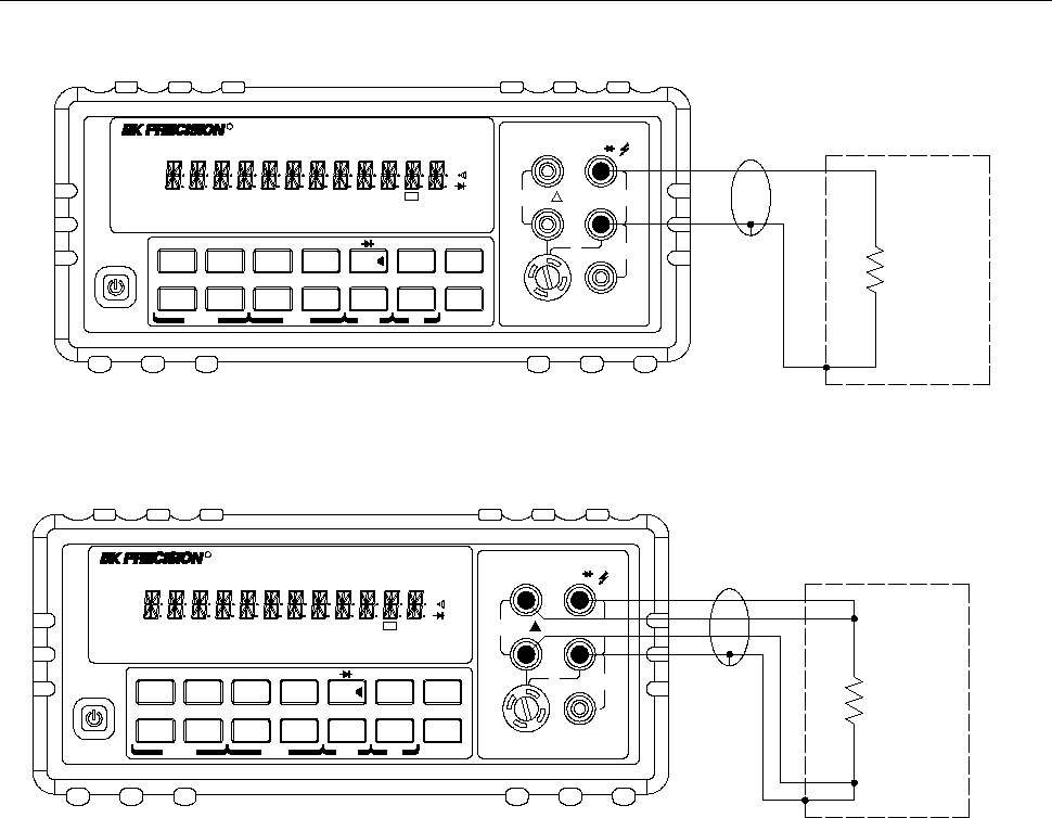
Figure 3-3 Two- and Four- wire Resistance Measurements
3.4.2 Shielding
To achieve a stable accurate reading, it helps to shield resistances greater than 100 kΩ. Place the
resistance in a shielded enclosure and connect the shield to the INPUT LO terminal of the instrument
electrically.