
User manual
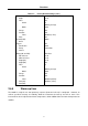
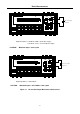
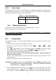
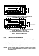
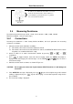
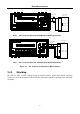
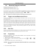
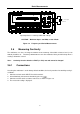
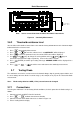
Table Of Contents
- 1.1 Feature Overview
- 1.2 Input Power and Fuse Requirements
- 1.3 Package Contents
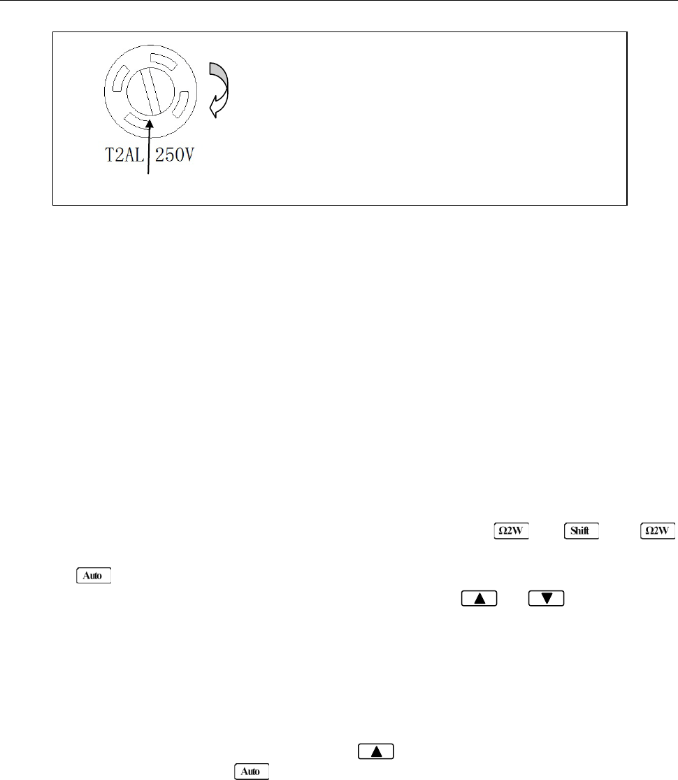
- 2.1 Front Panel Overview
- 2.2 Screen Display
- 2.3 Front Panel Menu Options
- 2.4 Front Panel Menu Overview
- Rear Panel Summary
- 2.6 Power up
- 3.1 Overview
- 3.2 Measuring Voltage
- 3.3 Measuring Current
- 3.4 Measuring Resistance
- 3.5 Measuring Frequency and Period
- 3.6 Measuring Continuity
- 3.7 Testing Diode
- 3.8 Math Functions
- 4.1 Measurement configuration
- 4.2 Trigger Operations
- 4.3 Buffer Operations
- 4.4 Limit Operations
- 4.5 System Operations
- 5.1 Selecting an Interface
- 5.2 USB & RS-232 Interface Operation
- 5.3 GPIB Interface operation (model 5492BGPIB only)
- 5.4 Data Format
- 6.1 Command Structure
- 6.2 Command Syntax
- 6.3 Command Reference
- 7.1 Frequently Asked Questions
- 7.2 Error Messages
- 8.1 Technical Specifications
Basic Measurements
26
3.4 Measuring Resistance
Resistance measurement range: 120 Ω, 1.2 kΩ, 12 kΩ, 120 kΩ, 1.2 MΩ, 12 MΩ, 120 MΩ
Maximum resolution: 1 mΩ (on 120 Ω range)
3.4.1 Connections
Assuming the multimeter is under factory default conditions, the basic procedure for measuring
resistance is as follows:
1. Connect test leads to the multimeter as follows:
A: For Ω2-wire, connect the test leads to INPUT HI and LO.
B: For Ω4-wire, connect the test leads to INPUT HI and LO, and SENSE Ω 4W HI and LO. Kelvin
test probes are recommended for this setup.
2. Select Ω 2-wire or Ω 4-wire measurement function by pressing or →
respectively.
3. Press to toggle between auto and manual ranging. Notice the AUTO annunciator is
displayed with auto ranging. For manual range, use the RANGE and keys to select a
measurement range.
4. Connect test leads to the resistance as shown in Figure 3-3:
CAUTION: Do not apply more than 1000 V peak between INPUT HI and LO or it will damage the
instrument
5. If the “OVR.FLW” message is displayed, press up key to select a higher range until a normal
reading is displayed (or press key for auto ranging). Use the lowest possible range for the
best resolution.
6. The measured reading is displayed.
Fuse Box
110
To remove, use a flat head screw driver or a coin to
insert into the slid and turn counter-clockwise to
open. Similarly to put back the fuse box, push the
box down and turn clockwise.