
User manual
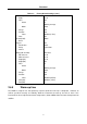
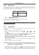
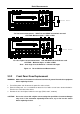
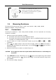
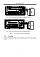
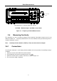
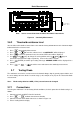
Table Of Contents
- 1.1 Feature Overview
- 1.2 Input Power and Fuse Requirements
- 1.3 Package Contents
- 2.1 Front Panel Overview
- 2.2 Screen Display
- 2.3 Front Panel Menu Options
- 2.4 Front Panel Menu Overview
- Rear Panel Summary
- 2.6 Power up
- 3.1 Overview
- 3.2 Measuring Voltage
- 3.3 Measuring Current
- 3.4 Measuring Resistance
- 3.5 Measuring Frequency and Period
- 3.6 Measuring Continuity
- 3.7 Testing Diode
- 3.8 Math Functions
- 4.1 Measurement configuration
- 4.2 Trigger Operations
- 4.3 Buffer Operations
- 4.4 Limit Operations
- 4.5 System Operations
- 5.1 Selecting an Interface
- 5.2 USB & RS-232 Interface Operation
- 5.3 GPIB Interface operation (model 5492BGPIB only)
- 5.4 Data Format
- 6.1 Command Structure
- 6.2 Command Syntax
- 6.3 Command Reference
- 7.1 Frequently Asked Questions
- 7.2 Error Messages
- 8.1 Technical Specifications

Overview
21
Table 2-2 Factory Default Settings (cont.)
Resistance(2-wire and 4-wire)
Digits
Filter
Count
Mode
Range
Relative
Value
Rate
RS-232(USB)
Baud
Triggers
Continuous
Delay
Source
Voltage(AC and DC)
dB reference
dBm reference
Digits(AC)
Digits(DC)
Filter
Count
Mode
Range
Relative
Value
Rate(AC)
Rate(DC)
5 1/2
On
5
Moving average
Auto
Off
0.0
Medium(1 PLC)
On
9600
On
Auto
Immediate
No effect
75 Ω
5 1/2
5 1/2
On
5
Moving average
Auto
Off
0.0
Medium(10PLC)
Medium( 1PLC)
2.6.5 Warm-up time
The 5492B is ready for use after power-up sequence (boot and self test) is completed. However, to
achieve specified accuracy and stability, allow the instrument to warm up for half an hour. If the
instrument has been subjected to extreme temperatures, allow additional time for internal temperature to
stabilize