
User manual
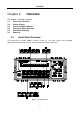
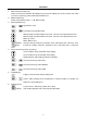
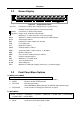
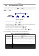
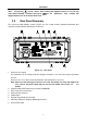
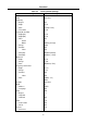
Table Of Contents
- 1.1 Feature Overview
- 1.2 Input Power and Fuse Requirements
- 1.3 Package Contents
- 2.1 Front Panel Overview
- 2.2 Screen Display
- 2.3 Front Panel Menu Options
- 2.4 Front Panel Menu Overview
- Rear Panel Summary
- 2.6 Power up
- 3.1 Overview
- 3.2 Measuring Voltage
- 3.3 Measuring Current
- 3.4 Measuring Resistance
- 3.5 Measuring Frequency and Period
- 3.6 Measuring Continuity
- 3.7 Testing Diode
- 3.8 Math Functions
- 4.1 Measurement configuration
- 4.2 Trigger Operations
- 4.3 Buffer Operations
- 4.4 Limit Operations
- 4.5 System Operations
- 5.1 Selecting an Interface
- 5.2 USB & RS-232 Interface Operation
- 5.3 GPIB Interface operation (model 5492BGPIB only)
- 5.4 Data Format
- 6.1 Command Structure
- 6.2 Command Syntax
- 6.3 Command Reference
- 7.1 Frequently Asked Questions
- 7.2 Error Messages
- 8.1 Technical Specifications

Overview
20
Table 2-2 Factory Default Settings
Setting Factory Default
Autozero
Buffer
Continuity
Beeper
Digits
Rate
Threshold
Current(AC and DC)
Digits(AC)
Digits(DC)
Filter
Count
Mode
Range
Relative
Value
Rate(AC)
Rate(DC)
Diode test
Digits
Range
Rate
Frequency and Period
Digits
Range
Relative
Value
Rate
Function
GPIB
Address
Language
Limits
Beeper
High limit
Low limit
mX+b
Scale factor
Offset
Percent
Reference
On
No effect
On
4 1/2
Fast(0.1 PLC)
10 Ω
5 1/2
5 1/2
On
5
Moving average
Auto
Off
0.0
Medium(10PLC)
Medium( 1 PLC)
5 1/2
1 mA
Medium(1 PLC)
5 1/2
12 V
Off
0.0
Slow(1 sec)
DCV
No effect
8
SCPI
Off
ON
+1
-1
Off
1.0
0.0
Off
1.0