
User manual
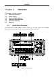
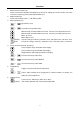
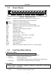
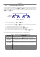
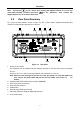
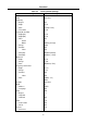
Table Of Contents
- 1.1 Feature Overview
- 1.2 Input Power and Fuse Requirements
- 1.3 Package Contents
- 2.1 Front Panel Overview
- 2.2 Screen Display
- 2.3 Front Panel Menu Options
- 2.4 Front Panel Menu Overview
- Rear Panel Summary
- 2.6 Power up
- 3.1 Overview
- 3.2 Measuring Voltage
- 3.3 Measuring Current
- 3.4 Measuring Resistance
- 3.5 Measuring Frequency and Period
- 3.6 Measuring Continuity
- 3.7 Testing Diode
- 3.8 Math Functions
- 4.1 Measurement configuration
- 4.2 Trigger Operations
- 4.3 Buffer Operations
- 4.4 Limit Operations
- 4.5 System Operations
- 5.1 Selecting an Interface
- 5.2 USB & RS-232 Interface Operation
- 5.3 GPIB Interface operation (model 5492BGPIB only)
- 5.4 Data Format
- 6.1 Command Structure
- 6.2 Command Syntax
- 6.3 Command Reference
- 7.1 Frequently Asked Questions
- 7.2 Error Messages
- 8.1 Technical Specifications

Overview
19
2.6.3 High Energy Circuit Safety Precautions
To optimize safety when measuring voltage in high energy distribution circuits, read and use the
directions in the following warning.
WARNIG: Dangerous arcs of an explosive nature in a high energy circuit can cause severe
personal injury or death. If the multimeter is connected to a high energy circuit
when set to a current range, low resistance range, or any other low impedance
range, the circuit is virtually shorted. Dangerous arcing can result even when the
multimeter is set to a voltage range if the minimum voltage spacing is reduced in the
external connections.
When making measurements in high energy circuits, use test leads and accessories that meet the
following requirements:
Test leads and accessories must be fully insulated and adhere to proper ANSI IEC CAT ratings.
Do not use test leads or accessories that decrease voltage spacing. This diminishes arc
protection and creates a hazardous condition.
WARNING: The maximum common-mode voltage (voltage between INPUT LO and the chassis
ground) is 500 V peak. Exceeding this value may cause a breakdown in insulation,
creating a shock hazard.
2.6.4 Power-on Defaults
The multimeter uses the factory default settings for the power-on settings.
All the procedures in this manual assume factory default settings, therefore reset the instrument to the
factory settings when following the step-by-step procedures in later sections. Table 2-2 lists the factory
default settings.