
User manual
Table Of Contents
- 1.1 Feature Overview
- 1.2 Input Power and Fuse Requirements
- 1.3 Package Contents
- 2.1 Front Panel Overview
- 2.2 Screen Display
- 2.3 Front Panel Menu Options
- 2.4 Front Panel Menu Overview
- Rear Panel Summary
- 2.6 Power up
- 3.1 Overview
- 3.2 Measuring Voltage
- 3.3 Measuring Current
- 3.4 Measuring Resistance
- 3.5 Measuring Frequency and Period
- 3.6 Measuring Continuity
- 3.7 Testing Diode
- 3.8 Math Functions
- 4.1 Measurement configuration
- 4.2 Trigger Operations
- 4.3 Buffer Operations
- 4.4 Limit Operations
- 4.5 System Operations
- 5.1 Selecting an Interface
- 5.2 USB & RS-232 Interface Operation
- 5.3 GPIB Interface operation (model 5492BGPIB only)
- 5.4 Data Format
- 6.1 Command Structure
- 6.2 Command Syntax
- 6.3 Command Reference
- 7.1 Frequently Asked Questions
- 7.2 Error Messages
- 8.1 Technical Specifications
General information
10
There is a second fuse with a fuse holder located in the front panel of the multimeter. This is an over
current protection fuse for the low current measurement input. It is rated for a T2AL, 250 V fuse. To
remove and replace this fuse, see the illustration below:
There is a third fuse located inside the instrument which protects the 12 A input terminal if current
exceeds the maximum rating. It is a 6 x 32 mm 250V, 20 A fast acting high energy ceramic fuse.
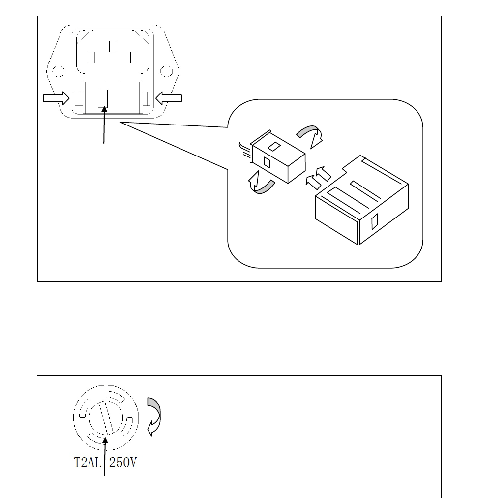
Fuse Box
110
To remove, use a flat head screw driver or a coin to
insert into the slid and turn counter-clockwise to
open. Similarly to put back the fuse box, push the
box down and turn clockwise.
Voltage Indicator Window
Fuse Holder
Fuse Box
110
110
220
Press both sides indicated by the arrows and pull to
remove fuse box.