©Copyright 2005 by Bird Electronic Corporation Instruction Book Part Number 920-4027AS Rev.
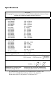
Specifications CAUTION Changing the sensor’s connectors will invalidate calibration data, and may reduce the maximum power rating of the unit. Frequency Range 4027A250K 4027A400K 4027A800K 4027A2M 4027A4M 4027A10M 4027A12M 4027A25M 4027A35M 4027A60M 4027A100M 4027A150M 250 – 400 kHz 400 – 550 kHz 800 – 950 kHz 1.5 – 2.
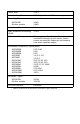
VSWR, Max 1.05:1 Insertion Loss, Max 0.05 dB (with female “N” connectors) Directivity, Min 4027A12M All other models 30 dB 28 dB Impedance, Nominal 50 ohms Max. Allowable Terminating VSWR 2.00:1 Calibration Technique Frequency-specific calibration factors stored in nonvolatile memory in each sensor. Sensor output corrected for frequency and temperature within specified ranges.
Connectors Customer specified from “QC” list, appropriate for frequency and power. Operating Power Supplied by power meter via sensor cable Sampling Rate, Nominal 2 readings / second Temperature Operating Storage 0 to 50 °C (32 to 122 ºF) –20 to +70 °C (–4 to +158 °F) Humidity, Max 95% (non-condensing) Altitude, Max 10,000 ft. (3,000 m) CE CE Compliant. Refer to Declaration of Conformity for specific standards Dimensions, Nominal 5.2”L x 2.5”W x 3.
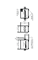
RF CONNECTORS (FEMALE N SHOWN) DIRECTIONAL POWER SENSOR MODEL 4027A2M 3W – 10kW 1.5 – 2.5 MHz 3-3/4” (95 mm) 3/4” (19 mm) 1-3/8” (35 mm) 2-1/2” (64 mm) SOURCE – CAUTION – 12000 WATTS MAX.
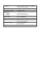
Special Lifetime Warranty – Series 4027A Power Sensor Head In addition to its standard warranty, the Bird Electronic Corporation warrants its Series 4027A Thruline® Power Sensor Heads for lifetime to original purchaser. This extended warranty is against burnout.