
Instruction Manual


TX RX Systems Inc. Manual 7-9100-5 10/17/11 Page 2
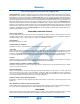
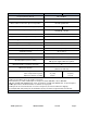
Specifications (Note 1) 73-90-11-2C-nn 73-90-11-2D-nn
Frequency Range (Note 2) 806 - 960 MHz
Cavity Type and Diameter 3/4-wave 6.625” (168 mm)
Max Continuous TX Power @ Tx-Tx Separation
150 Watts @ 450 KHz
125 watts @ 250 KHz
Isolator Load Power (Continuous) (Note 3) 5W / 60W 5W / 100W
Minimum TX-TX Separation @ Cavity Loss
450 KHz @ -1.25 dB
250 KHz @ -1.80 dB
Channel Insertion Loss See Table 2.
Typical TX-TX Isolation @ Minimum Separation -80 dB
Typical Antenna-TX Isolation -70 dB
Typical TX Noise Suppression See Figure 2.
Nominal Input Impedance, Ohms 50
Maximum Input Return Loss (VSWR) -20 dB (1.22:1)
Temperature Range -30° to +60° C
Connectors, Input and Antenna N(F)
Mechanical Mounting Peg Rack™ included with system
Mounting Options (Notes 4 and 5)
-MC: 14” H x 19” W rack-mount adaptor plates
-LR: System supplied without Peg-Rack
Maximum Number of Channels Per Rack 15
Dimensions (Note 6)
65.25” H x 24” W x 20.7” D
(1659 x 610 x 526 mm)
Weight, lb. (Kg)
Basic single-channel system:
Expansion channel assembly:
31 (14.0)
12 (5.4)
32 (14.5)
13 (5.9)
Notes:
1.-nn in model number represents number of channels.
2.Consult factory on T-Pass multicouplers for frequencies below 806 MHz or above 960 MHz.
3.Models available with 5W/25W loads. Same specifications as 60W and 100W models, except load power.
4. -MC option reduces maximum number of channels to 12 per pack.
5. -LR systems are tuned and tested on customer frequencies, then disassembled for shipping.
6. rack depth with cavity tuning rods at maximum frequency. Rod travel is approximately 2.2” (56 mm).
Table 1: Specifications.